Mitsubishi Galant. Manual - part 628


  Index      Mitsubishi     Mitsubishi Galant - service repair manual 2001 year


Search            


Content   ..  626  627  628  629   ..


Mitsubishi Galant. Manual - part 628


COMBINATION METERS ASSEMBLY AND VEHICLE SPEED SENSOR

TSB Revision

CHASSIS ELECTRICAL

54A-65

COMBINATION METERS ASSEMBLY AND VEHICLE SPEED SENSOR

REMOVAL AND INSTALLATION

M1543002900140

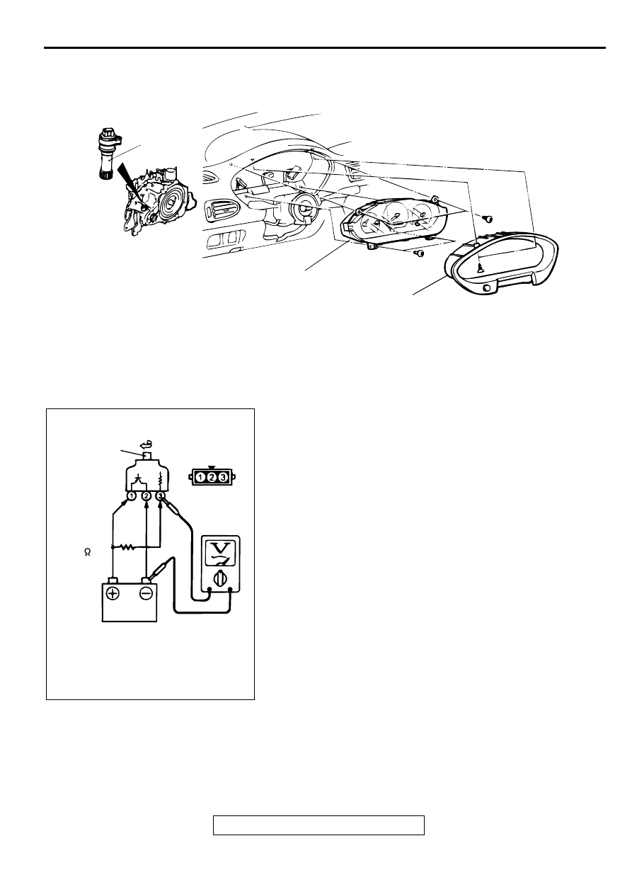
VEHICLES SPEED SENSOR CHECK

M1543006400103

1. Remove the vehicle speed sensor and connect a 3 

 10 k


resistor as shown in the illustration.

2. Turn the shaft of the vehicle speed sensor and check that 

there is voltage between terminals 2 

 3. (1 turn = 4 pulses)

3. If within the standard value, the vehicle speed sensor is OK.

If not within the standard value, replace the vehicle speed 
sensor.

AC002890AB

1

2

3

VEHICLE SPEED SENSOR 
REMOVAL STEPS

AIR CLEANER ASSEMBLY

1.

VEHICLE SPEED SENSOR

COMBINATION METER REMOVAL 
STEPS

2. METER BEZEL
3. COMBINATION METER

ACX01647

TURN

SHAFT

AC

RESISTOR
3 - 10

TSB Revision

CHASSIS ELECTRICAL

COMBINATION METERS ASSEMBLY AND VEHICLE SPEED SENSOR

54A-66

FUEL GAUGE RESISTANCE CHECK

M1543003000106

CAUTION

When inserting a testing probe into the power supply 
terminal, be careful not to touch the printed board.
1. Remove the power supply tightening screw.

2. Use an ohmmeter to measure the resistance value between 

the terminals.

Standard value:

Power supply 

−−−−

 Ground: Approximately 95 

Power supply 

−−−−

 Fuel gauge: Approximately 87 

Fuel gauge 

−−−−

 Ground: Approximately 98 

3. If within the standard value, the fuel gauge is OK.

4. If not within the standard value, replace the fuel gauge and 

engine coolant temperature gauge.

ENGINE COOLANT TEMPERATURE GAUGE 
RESISTANCE CHECK

M1543013400042

CAUTION

When inserting a testing probe into the power supply 
terminal, be careful not to touch the printed board.
1. Remove the power supply tightening screw.

2. Use an ohmmeter to measure resistance value between the 

terminals.

Standard value:

Power supply 

−−−−

 Ground: Approximately 95 

Power supply 

−−−−

 Engine coolant temperature gauge: 

Approximately 75 

Engine coolant temperature gauge 

−−−−

 Ground: 

Approximately 170 

3. If within the standard value, the engine coolant temperature 

gauge is OK.

4. If not within the standard value, replace the fuel gauge and 

engine coolant temperature gauge.

AC002891AB

POWER
SUPPLY

GROUND

FUEL GAUGE

AC002892

POWER
SUPPLY

ENGINE COOLANT
TEMPERATURE GAUGE

GROUND

AB

COMBINATION METERS ASSEMBLY AND VEHICLE SPEED SENSOR

TSB Revision

CHASSIS ELECTRICAL

54A-67

DISASSEMBLY AND REASSEMBLY

M1543003100103

DISASSEMBLY SERVICE POINT

CAUTION

Be careful not to damage the printed-circuit board when 
using a flat-tipped screwdriver.
<<A>> ODOMETER AND TRIPMETER REMOVAL
Unfasten the claw in the connector using a flat-tipped 
screwdriver to disconnect the connector.
Then remove the printed circuit board position, and remove the 
odometer and tripmeter.

AC002893

1

2

1

1

9

10

7

5

8

6

3

4

AB

DISASSEMBLY STEPS

1. BULB AND SOCKET

<<A>>

2. ODOMETER AND TRIPMETER
3. METER GLASS
4. WINDOW PLATE

5. TACHOMETER
6. SPEEDOMETER
7. TRIP COUNTER RESET KNOB
8. FUEL GAUGE AND ENGINE COOL-

ANT TEMPERATURE GAUGE

9. PRINTED-CIRCUIT BOARD
10. METER CASE

AC002894AB

ODOMETER
AND
TRIPMETER

CONNECTOR

CLAW

TSB Revision

CHASSIS ELECTRICAL

HEADLIGHT, FRONT SIDE MARKER LIGHT AND POSITION LIGHT ASSEMBLY

54A-68

H EA D LIG H T, FR O N T SID E M A R K ER  LIG H T A N D  PO SITIO N  

LIG H T ASSEM B LY

TAILLIGHT, HEADLIGHT AND TURN-SIGNAL LIGHT DIAGNOSIS

M1542000700277

The taillights, headlights and turn-signal lights are 
controlled by the Simplified Wiring System (SWS). 
For troubleshooting, refer to GROUP 54B, SWS 
Diagnosis 

P.54B-9

.

ON-VEHICLE SERVICE

HEADLIGHT AIMING

M1542000900099

PRE-AIMING INSTRUCTIONS

1. Inspect for badly rusted or faulty headlight assemblies.

2. These conditions must be corrected before a satisfactory 

adjustment can be made.

3. Place the vehicle on a level floor.

4. Bounce the front suspension through three (3) oscillations 

by applying the body weight to hood or bumper.

5. Inspect tire inflation, and adjust if necessary.

6. Rock vehicle sideways to allow vehicle to assume its normal 

position.

7. If the fuel tank is not full, place a weight in luggage room of 

vehicle to simulate weight of a full tank [3 kg (6.5 pounds) 
per gallon.]

8. There should be no other load in the vehicle other than 

driver or substituted weight of approximately 70 kg (150 
pounds) placed in driver's position.

9. Thoroughly clean headlight lenses.

AIMING WITH SCREEN OR WALL

Headlight Aim preparation
1. Set the distance between the screen and the bulb center 

marks of the headlight as shown in the illustration.

AC002895

CENTER MARK

AB


Content   ..  626  627  628  629   ..