Mitsubishi Galant. Manual - part 613


  Index      Mitsubishi     Mitsubishi Galant - service repair manual 2001 year


Search            


Content   ..  611  612  613  614   ..


Mitsubishi Galant. Manual - part 613


BATTERY

TSB Revision

CHASSIS ELECTRICAL

54A-5

.

B ATTERY

ON-VEHICLE SERVICE

BATTERY CHECK

M1541001000126

WARNING

Battery posts, terminals and related accessories 
contain lead and lead compounds. WASH HANDS 
AFTER HANDLING.

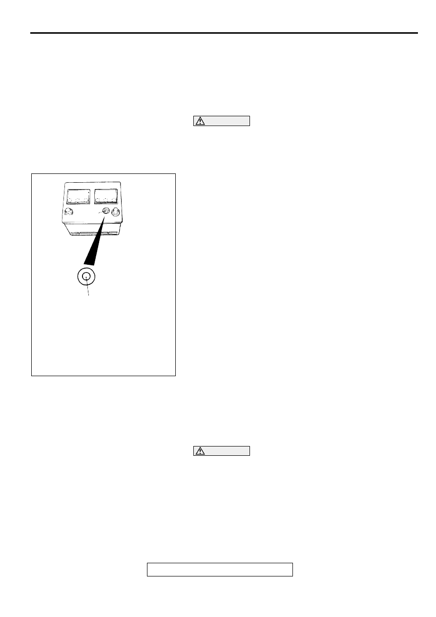
BATTERY VISUAL INSPECTION (1) 

The battery contains a visual test indicator which gives a blue 
signal when an adequate charge level exists, and a white 
signal when charging is required.

BATTERY VISUAL INSPECTION (2)  

Make sure ignition switch is in "LOCK"(OFF) position and all 
battery feed accessories are OFF.
1. Disconnect the negative cable from battery before 

disconnecting the positive cable.

WARNING

Care should be taken in the event battery case is 
cracked or leaking to protect hands from the 
electrolyte. A suitable pair of rubber gloves (not the 
household type) should be worn when removing 
battery by hand.

2. Remove the battery from the vehicle.

ACX01557

INDICATOR

AB

DARK EYE:CHARGING NECESSARY
GREEN:GOOD CONDIOTION

TSB Revision

CHASSIS ELECTRICAL

BATTERY

54A-6

3. Inspect battery carrier for damage caused by loss of acid 

from battery. If acid damage is present, it is necessary to 
clean area with a solution of clean warm water and baking 
soda. Scrub area with a stiff bristle brush. Wipe clean with a 
cloth moistened with ammonia or baking soda in water.

4. Clean the battery, especially the top with same solutions as 

described in step 3.

5. Inspect the battery case and cover for cracks. If cracks are 

present, battery must be replaced.

6. Clean the battery post with a suitable battery post cleaning 

tool.

7. Clean the inside surfaces of the terminal clamps with a 

suitable battery terminal cleaning tool. Replace damaged or 
frayed cables and broken terminal clamps.

8. Install the battery in the vehicle.

9. Connect the positive and negative cables to the battery in 

the order of mention.

10.Tighten the clamp nut securely.

BATTERY CHARGING

M1541001100101

WARNING

When batteries are being charged, an explosive gas forms beneath the cover of each cell. Do 
not smoke near batteries on charge or which have recently been charged. Do not break live 
circuits at the terminals of the batteries on charge. A spark will occur where the live circuit is 
broken. Keep all open flames away from the battery.

Battery electrolyte temperature may temporarily be allowed to rise to 55C

°

 (131F

°).

 Increase of electrolyte 

temperature above 55C 

°

 (131F

°) 

is harmful to the battery, causing deformation of battery cell, decrease in 

life of battery, etc.

CHARGE RATE 

If the test indicator is white, the battery should be 
charged as outlined below. When the dot appears or 
when maximum charge shown below is reached, 
charging should be stopped.

Charge Rate Chart

BATTERY TESTING PROCEDURE

M1541001200108

STEP 1. Check the battery cables.
Remove the negative cable, then the positive cable.
Check for dirty or corroded connections.

Q: Are the battery cables dirty or have corroded 

connections?

YES : 

Clean the battery cables. Then go to Step 2.

NO : 

Go to Step 2.

BATTERY

BCI Group size 86

Slow charging

5 amps 15 hours

10 amps 7.5 hours

Fast charging

20 amps 3.75hours

30 amps 2.5 hours

BATTERY

TSB Revision

CHASSIS ELECTRICAL

54A-7

STEP 2. Check the battery post.
Check for loose battery post.

Q: Are the battery post faulty? 

Yes : 

Replace the battery. Then go to Step 4 .

NO : 

Go to Step 3 .

STEP 3. Check the battery case and cover.
(1) )Remove the hold-downs and shields.
(2) Check for broken/cracked case or cover.

Q: Is the battery case or cover faulty?

YES : 

Replace the battery. Then go to Step 4 .

NO : 

Go to Step 4 .

STEP 4. Check the open circuit voltage.
(1) Turn headlights on for 15 seconds.
(2) Turn headlights off for two minutes to allow 

battery positive voltage to stabilize.

(3) Disconnect the battery cables.
(4) Read open circuit voltage.

Q: Is open circuit voltage 12.4 volts or more?

NO : 

Go to Step 5 .

YES : 

Go to Step .

STEP 5. Charge battery.

Q: Charging the battery?

YES : 

Charge the battery at 5 amps for 15 hours. 

Then re-test, go to Step 4 .

NO : 

Go to Step6.

STEP 6. Check the load test.
(1) Connect a load tester to the battery.
(2) Load the battery at the recommended discharge 

rate (See LOAD TEST RATE CHART) for 15 
seconds.

(3) Read voltage after 15 seconds, then remove 

load.

(4) Compare the measured value with the minimum 

voltage. (See LOAD TEST CHART.)

Q: Is the voltage higher than minimum voltage?

NO : 

Replace the battery. Then go to Step 4.

YES : 

The battery is normal.

LOAD TEST RATE CHART

LOAD TEST CHART

Load test

252 amps

Cranking ratio (0

°

F)

525 amps

Reserve capacity

90 minutes

Application

BCI Group size 86

TEMPERATURE  

°°°°

C (

°°°°

F)

21 (70) 
AND 
ABOVE

16 (60)

10 (50)

4 (40)

−−−−

1 (30)

−−−−

7 (20)

−−−−

12 (10)

−−−−

18 (0)

Minimum voltage

9.6

9.5

9.4

9.3

9.1

8.9

8.7

8.5

TSB Revision

CHASSIS ELECTRICAL

IGNITION SWITCH

54A-8

REMOVAL AND INSTALLATION

M1541001300075

IG N ITIO N  SW ITC H

GENERAL DESCRIPTION

M1543009900293

Ignition key reminder tone alarm

The ignition key reminder torn alarm will sound under 
the following condition, and warn the driver to 
remove the ignition key.

The driver's door is opened when the ignition 
switch is at "LOCK" (OFF) or "ACC" position 
without removing the ignition key.

However, the light reminder tone alarm will take 
precedence over this function. 

Ignition key hole illumination light

When the driver's door is opened (door switch ON) 
with the ignition key at "LOCK" (OFF), the ignition 
key hole illumination light will come on.

AC002875

1

2

3

4

AB

REMOVAL STEPS

1.

ACCELERATOR CABLE CLAMP

2.

BATTERY HOLDER

3.

BATTERY COVER

4.

BATTERY

REMOVAL STEPS


Content   ..  611  612  613  614   ..