Mitsubishi Galant. Manual - part 404


  Index      Mitsubishi     Mitsubishi Galant - service repair manual 2001 year


Search            


Content   ..  402  403  404  405   ..


Mitsubishi Galant. Manual - part 404


AUTOMATIC TRANSAXLE DIAGNOSIS

TSB Revision

AUTOMATIC TRANSAXLE

23A-83

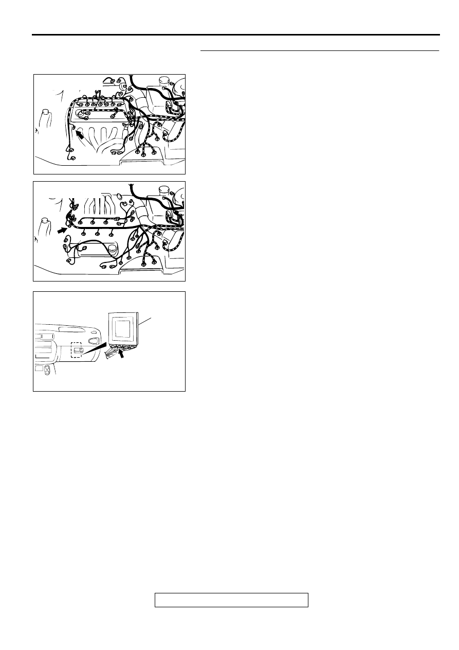
STEP 3. Check connectors B-20 at crankshaft position 
sensor and C-40 at PCM for damage.
Q: Are the connectors in good condition?

YES : Go to Step 4.
NO :  Repair or replace it. Refer to GROUP 00E, Harness 

Connector Inspection 

P.00E-2

.

AC004909

CONNECTOR: B-20
<2.4L ENGINE>

AB

AC004910

CONNECTOR: B-20
<3.0L ENGINE>

AB

AC004197

PCM

AD

CONNECTOR: C-40

AUTOMATIC TRANSAXLE DIAGNOSIS

TSB Revision

AUTOMATIC TRANSAXLE

23A-84

STEP 4. Using scan tool MB991502, check data list item 21: 
Crankshaft Position Sensor.

CAUTION

To prevent damage to scan tool MB991502, always turn the 
ignition switch to "LOCK" (OFF) position before 
connecting or disconnecting scan tool MB991502.
(1) Connect scan tool MB991502 to the data link connector.
(2) With the gear selector lever in the "P" position, start the 

engine and run at idle.

(3) Set scan tool MB991502 to data reading mode for item 21: 

Crankshaft Position Sensor.

When the accelerator pedal is not depressed (throttle 
valve is fully closed) the display should be "600 to 900 r/
min."

With the accelerator pedal depressed, the engine speed 
should increase according to engine speed.

Q: Is the sensor operating properly?

YES : This malfunction is intermittent. Refer to GROUP 00, 

How to Use Troubleshooting/Inspection Service 
Points 

 How to Cope with Intermittent Malfunction 

P.00-8

.

NO :  Replace the PCM.

STEP 5. Check connector B-20 at crankshaft position 
sensor for damage.
Q: Is the connector in good condition?

YES : Go to Step 6.
NO :  Repair or replace it. Refer to GROUP 00E, Harness 

Connector Inspection 

P.00E-2

.

AC003081AC

MB991502

DATA LINK
CONNECTOR

AC004909

CONNECTOR: B-20
<2.4L ENGINE>

AB

AC004910

CONNECTOR: B-20
<3.0L ENGINE>

AB

AUTOMATIC TRANSAXLE DIAGNOSIS

TSB Revision

AUTOMATIC TRANSAXLE

23A-85

STEP 6. Check the sensor output voltage at crankshaft 
position sensor connector B-20.
(1) Disconnect connector B-20 and measure at the harness 

side.

(2) Turn the ignition switch to "ON" position.

(3) Measure the voltage between terminal 2 and ground.

Voltage should be between 4.8 and 5.2 volts.

(4) Turn the ignition switch to "LOCK" (OFF) position.

Q: Is the voltage normal?

YES : Go to Step 11.
NO :  Go to Step 7.

AC004909

CONNECTOR: B-20
<2.4L ENGINE>

AB

AC004910

CONNECTOR: B-20
<3.0L ENGINE>

AB

ACX02114

HARNESS
CONNECTOR: B-20

AC

AUTOMATIC TRANSAXLE DIAGNOSIS

TSB Revision

AUTOMATIC TRANSAXLE

23A-86

STEP 7. Check the sensor output voltage at PCM 
connector C-40 by backprobing.
(1) Do not disconnect connector C-40.
(2) Disconnect connector B-20 at crankshaft position sensor.
(3) Turn the ignition switch to the "ON" position.

(4) Measure the voltage between terminal 45 and ground by 

backprobing.

Voltage should be between 4.8 and 5.2 volts.

(5) Turn the ignition switch to "LOCK" (OFF) position.

Q: Is the voltage normal?

YES : Go to Step 8.
NO :  Go to Step 9.

STEP 8. Check connector C-40 at PCM for damage.
Q: Is the connector in good condition?

YES : Repair it because of harness open circuit between 

crankshaft position sensor connector B-20 terminal 2 
and PCM connector C-40 terminal 45.

NO :  Repair or replace it. Refer to GROUP 00E, Harness 

Connector Inspection 

P.00E-2

.

STEP 9. Check connector C-40 at PCM for damage.
Q: Is the connector in good condition?

YES : Go to Step 10.
NO :  Repair or replace it. Refer to GROUP 00E, Harness 

Connector Inspection 

P.00E-2

.

AC004197

PCM

AD

CONNECTOR: C-40

AC001806

C-40 CONNECTOR
HARNESS SIDE VIEW

AE

AC004197

PCM

AD

CONNECTOR: C-40

AC004197

PCM

AD

CONNECTOR: C-40


Content   ..  402  403  404  405   ..