Mitsubishi Galant. Manual - part 397


  Index      Mitsubishi     Mitsubishi Galant - service repair manual 2001 year


Search            


Content   ..  395  396  397  398   ..


Mitsubishi Galant. Manual - part 397


AUTOMATIC TRANSAXLE DIAGNOSIS

TSB Revision

AUTOMATIC TRANSAXLE

23A-55

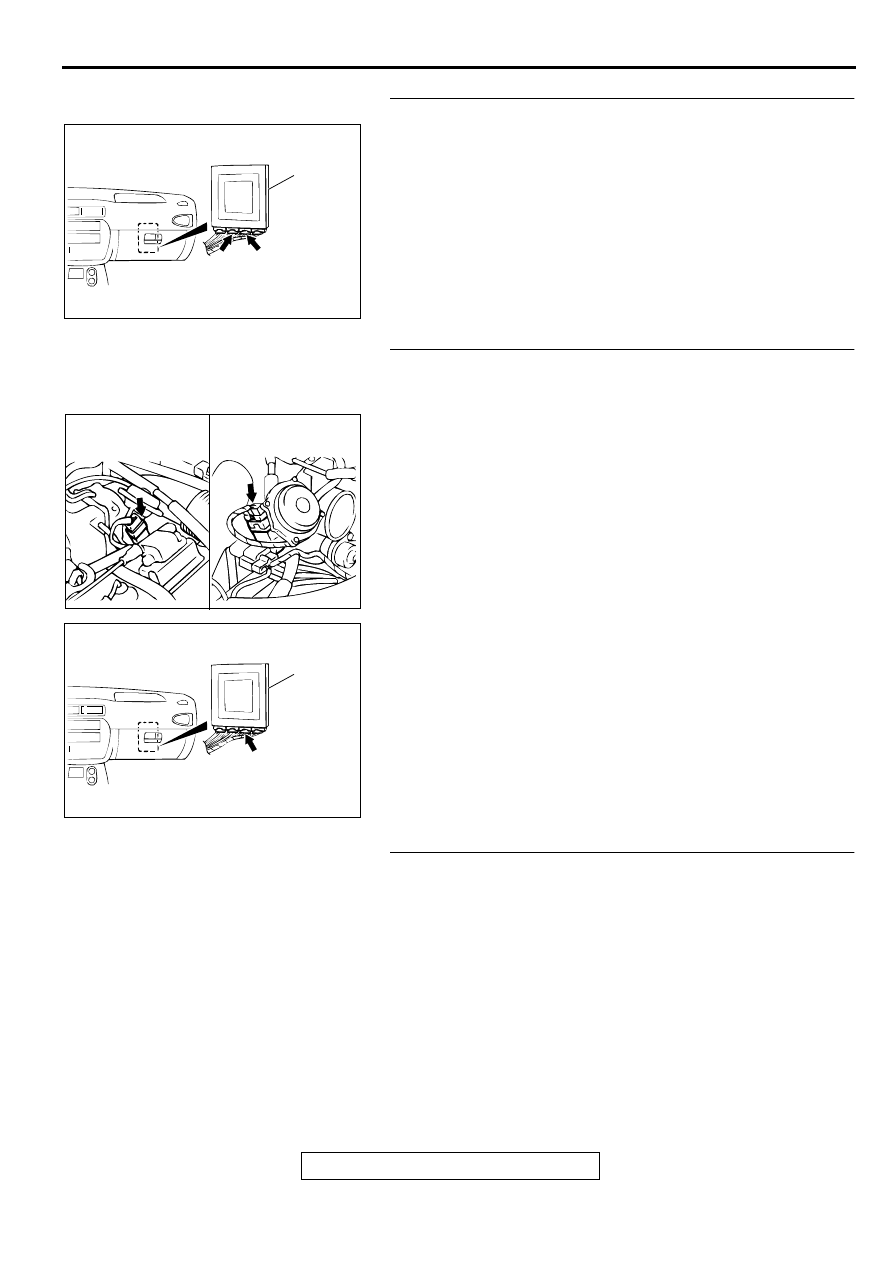
STEP 14. Check connectors C-40, C-41 at PCM for damage.
Q: Are the connectors in good condition?

YES : Go to Step 15.
NO :  Repair or replace it. Refer to GROUP 00E, Harness 

Connector Inspection 

P.00E-2

.

STEP 15. Check harness for short circuit to ground or 
damage between throttle position sensor connector B-05 
terminal 3 and PCM connector C-41 terminal 78.
Q: Is the harness wire in good condition?

YES : Go to Step 16.
NO :  Repair it.

STEP 16. Check the connector and the harness for short 
circuit to ground between the throttle position sensor 
connector and the auto-cruise control-ECU connector.

Q: Is the harness wire in good condition?

YES : Throttle position sensor adjustment. Refer to GROUP 

13A <2.4L Engine>, On-vehicle Service 

 Throttle 

Position Sensor Adjustment 

P.13A-437

 or 13B <3.0L 

Engine>, On-vehicle Service 

 Throttle Position 

Sensor Adjustment 

P.13B-519

.

NO :  Repair it.

AC004197

PCM

C-40

C-41

CONNECTORS: C-40, C-41

AB

AC001831AD

CONNECTOR: B-05

<2.4L ENGINE>

<3.0L ENGINE>

AC004197

PCM

AC

CONNECTOR: C-41

AUTOMATIC TRANSAXLE DIAGNOSIS

TSB Revision

AUTOMATIC TRANSAXLE

23A-56

DTC 14: Throttle Position  Sensor System (Maladjusted Sensor)

Throttle Position Sensor System Circuit
Refer to 

P.23A-39

.

CIRCUIT OPERATION
Refer to 

P.23A-39

.

DTC SET CONDITIONS
 If TPS output voltage is 0.2 volts or lower or if it is 
1.2 volts or higher when the engine is idling, the TPS 
adjustment is judged to be incorrect and diagnostic 
trouble code number "14" is output.

TROUBLESHOOTING HINTS (The most likely 

causes for this code to be set:)

Malfunction of the throttle position sensor circuit

Damaged harness, connector

Malfunction of the PCM

DIAGNOSIS

Required Special Tool:
MB991502: Scan Tool (MUT-II)

STEP 1. Using scan tool MB991502, read the A/T 
diagnostic trouble code.

CAUTION

To prevent damage to scan tool MB991502, always turn the 
ignition switch to the "LOCK" (OFF) position before 
connecting or disconnecting scan tool MB991502.
(1) Connect scan tool MB991502 to the data link connector.
(2) Turn the ignition switch to "ON" position.
(3) Read the A/T diagnostic trouble code.
(4) Turn the ignition switch to "LOCK" (OFF) position.

Q: Is the A/T diagnostic trouble code number "11" or "12" 

output?
YES : 
Refer to 

P.23A-39

code number 11: Throttle Position 

Sensor System (Short Circuit), 

P.23A-48

 code 

number 12: Throttle Position Sensor System (Open 
Circuit).

NO :  Go to Step 2.

STEP 2. Using scan tool MB991502, check data list item 11: 
Throttle Position Sensor.
(1) Connect scan tool MB991502 to the data link connector.
(2) Turn the ignition switch to "ON" position.
(3) Set scan tool MB991502 to data reading mode for item 11: 

Throttle Position Sensor.

With the throttle valve in idle position, voltage should be 
between 535 and 735 mV.

With the throttle valve in full-open position, voltage 
should be between 4,500 and 5,500 mV.

(4) Turn the ignition switch to "LOCK" (OFF) position.

Q: Is the sensor operating properly?

YES : This malfunction is intermittent. Refer to GROUP 00, 

How to Use Troubleshooting/Inspection Service 
Points 

 How to Cope with Intermittent Malfunction 

P.00-8

.

NO :  Go to Step 3.

AC003081AC

MB991502

DATA LINK
CONNECTOR

AC003081AC

MB991502

DATA LINK
CONNECTOR

AUTOMATIC TRANSAXLE DIAGNOSIS

TSB Revision

AUTOMATIC TRANSAXLE

23A-57

STEP 3. Check the sensor output voltage at throttle 
position sensor connector B-05 by backprobing.
(1) Do not disconnect connector B-05.
(2) Turn the ignition switch to "ON" position.

(3) Measure the voltage between terminal 3 and ground by 

backprobing.

With the throttle valve in idle position, voltage should be 
between 0.535 and 0.735 volts.

With the throttle valve in full-open position, voltage 
should be between 4.5 and 5.5 volts.

(4) Turn the ignition switch to "LOCK" (OFF) position.

Q: Is the voltage normal?

YES : Go to Step 4.
NO :  Go to Step 8.

STEP 4. Check the sensor output voltage at PCM 
connector C-41 by backprobing.
(1) Do not disconnect connector C-41.
(2) Turn the ignition switch to "ON" position.

(3) Measure the voltage between terminal 78 and ground by 

backprobing.

With the throttle valve in idle position, voltage should be 
between 0.535 and 0.735 volts.

With the throttle valve in full-open position, voltage 
should be between 4.5 and 5.5 volts.

(4) Turn the ignition switch to "LOCK" (OFF) position.

Q: Is the voltage normal?

YES : Go to Step 5.
NO :  Go to Step 7.

AC001831AD

CONNECTOR: B-05

<2.4L ENGINE>

<3.0L ENGINE>

AC001548

B-05 CONNECTOR
HARNESS SIDE VIEW

AD

AC004197

PCM

AC

CONNECTOR: C-41

AC000847AE

C-41 CONNECTOR
HARNESS SIDE VIEW

AUTOMATIC TRANSAXLE DIAGNOSIS

TSB Revision

AUTOMATIC TRANSAXLE

23A-58

STEP 5. Check connectors B-05 at throttle position sensor 
and C-41 at PCM for damage.
Q: Are the connectors in good condition?

YES : Go to Step 6.
NO :  Repair or replace it. Refer to GROUP 00E, Harness 

Connector Inspection 

P.00E-2

.

STEP 6. Using scan tool MB991502, check data list item 11: 
Throttle Position Sensor.

CAUTION

To prevent damage to scan tool MB991502, always turn the 
ignition switch to "LOCK" (OFF) position before 
connecting or disconnecting scan tool MB991502.
(1) Connect scan tool MB991502 to the data link connector.
(2) Turn the ignition switch to "ON" position.
(3) Set scan tool MB991502 to data reading mode for item 11: 

Throttle Position Sensor.

With the throttle valve in idle position, voltage should be 
between 535 and 735 mV.

With the throttle valve in the full-open position, voltage 
should be between 4,500 and 5,500 mV.

(4) Turn the ignition switch to "LOCK" (OFF) position.

Q: Is the sensor operating properly?

YES : This malfunction is intermittent. Refer to GROUP 00, 

How to Use Troubleshooting/Inspection Service 
Points 

 How to Cope with Intermittent Malfunction 

P.00-8

.

NO :  Replace the PCM.

AC001831AD

CONNECTOR: B-05

<2.4L ENGINE>

<3.0L ENGINE>

AC004197

PCM

AC

CONNECTOR: C-41

AC003081AC

MB991502

DATA LINK
CONNECTOR


Content   ..  395  396  397  398   ..