Mitsubishi Galant. Manual - part 377
EMISSION CONTROL
TSB Revision
ENGINE AND EMISSION CONTROL
17-78
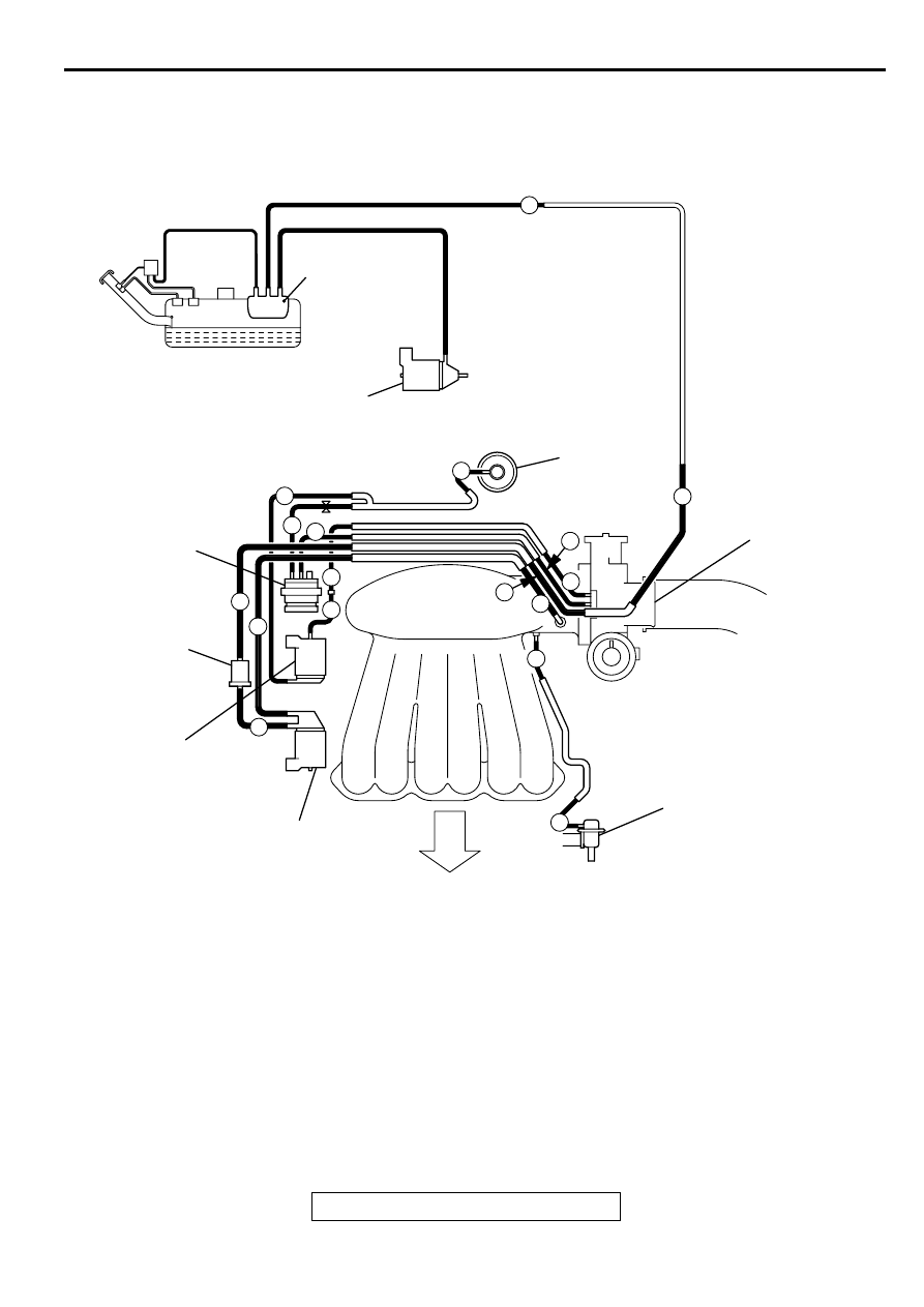
<3.0L ENGINE>
AKX01294
B: BLACK
G: GREEN
L: LIGHT BLUE
W: WHITE
Y: YELLOW
*1:RED PAINT MARK
*2:RESTRICTOR
EVAPORATIVE
EMISSION
CANISTER
EVAPORATIVE EMISSION
VENTILATION SOLENOID
EGR VALVE
THROTTLE BODY
VACUUM
CONTROL
VALVE
CHAMBER
EGR SOLENOID
FUEL PRESSURE
REGULATOR
EVAPORATIVE EMISSION
PURGE SOLENOID
FRONT
AB
B
B
B
B
B
B
B
B
B
B
G
W G
G
Y
Y
*1
*1
*2
L