Mitsubishi Galant. Manual - part 355


  Index      Mitsubishi     Mitsubishi Galant - service repair manual 2001 year


Search            


Content   ..  353  354  355  356   ..


Mitsubishi Galant. Manual - part 355


IGNITION SYSTEM

TSB Revision

ENGINE ELECTRICAL

16-46

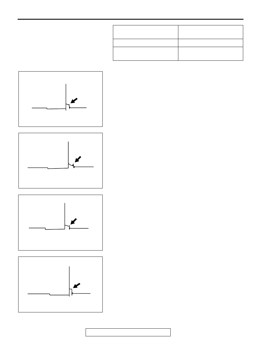
ABNORMAL WAVEFORMS EXAMPLES
Example 1

Wave characteristics
Spark line is high and short.

Cause of problem
Spark plug gap is too large.

Example 2

Wave characteristics
Spark line is low and long, and is sloping.
Also, the second half of the spark line is distorted. This 
could be a result of misfiring.

Cause of problem
Spark plug gap is too small.

Example 3

Wave characteristics
Spark line is low and long, and is sloping. However, 
there is almost no spark line distortion.

Cause of problem
Spark plug gap is fouled.

Example 4

Wave characteristics
Spark line is high and short

Cause of problem
Spark plug cable is not properly connected. (Causing a 
dual ignition)

HEIGHT OF ZENER 
VOLTAGE

PROBABLE CAUSE

High

Problem in zener diode

Low

Abnormal resistance in 
primary coil circuit

AKX00288

AKX00289

AKX00290

AKX00291

IGNITION SYSTEM

TSB Revision

ENGINE ELECTRICAL

16-47

Example 5

Wave characteristics
No waves in wave damping section

Cause of problem
Layer short in ignition coil.

IGNITION COIL

REMOVAL AND INSTALLATION <2.4L ENGINE>

M1163004000040

DISTRIBUTOR ASSEMBLY

REMOVAL AND INSTALLATION <3.0L ENGINE>

M1163002000055

AKX00292

AC000288

1

2

3

1

2

4

9.8 N·m
87 in-lb

9.8 N·m
87 in-lb

4.9 N·m
43  in-lb     

25 N·m
18 ft-lb

AC

REMOVAL STEPS

1.

SPARK PLUG CABLE

2.

IGNITION COIL ASSEMBLY

3.

SPARK PLUG

4.

IGNITION FAILURE SENSOR 
ASSEMBLY

REMOVAL STEPS (Continued)

Pre-removal Operation

Air Cleaner Removal (Refer to GROUP 15 

 Air Cleaner 

P.15-4

.)

Post-installation Operation

Air Cleaner Installation (Refer to GROUP 15 

 Air Cleaner 

P.15-4

.)

Ignition Timing Check (Refer to GROUP 11C, On-vehicle 
Service 

 Ignition Timing Check 

P.11C-5

.)

IGNITION SYSTEM

TSB Revision

ENGINE ELECTRICAL

16-48

INSTALLATION SERVICE POINT

>>A<< DISTRIBUTOR INSTALLATION
1. Set the number 1 cylinder to top dead compression center.

2. Align the mating marks on the distributor housing and 

coupling, and then install the distributor to the engine.

3. Check that the ignition timing is at the standard value. (Refer 

to GROUP 11C, On-vehicle-Service - Ignition Timing Check 

P.11C-5

.)

AC000289AC

1

2

4

5

2

3

4

5

12 N·m
106 in-lb

25 N·m
18 ft-lb

25 N·m
18 ft-lb

N

N

REMOVAL STEPS

1.

DISTRIBUTOR CONNECTOR

2.

SPARK PLUG CABLE 
CONNECTION

>>A<<

3.

DISTRIBUTOR

INTAKE MANIFOLD PLENUM 
(REFER TO GROUP 15 

 INTAKE 

MANIFOLD PLENUM 

P.15-5

.)

4.

SPARK PLUG CABLE

5.

SPARK PLUG

REMOVAL STEPS (Continued)

AC000290 AB

MATING
MARKS

IGNITION SYSTEM

TSB Revision

ENGINE ELECTRICAL

16-49

DISASSEMBLY AND ASSEMBLY

M1163002200059

CAMSHAFT POSITION SENSOR

REMOVAL AND INSTALLATION <2.4L ENGINE>

M1163003400089

AK000203AC

1

2

3

4

5

2.3 – 0.7  N•m
20 – 6 in-lb

DISASSEMBLY STEPS

1.

DISTRIBUTOR CAP

2.

ROTOR

3.

PACKING

4.

DISTRIBUTOR HOUSING

5.

O-RING

DISASSEMBLY STEPS 

AC000291

CAMSHAFT POSITION
SENSOR

8.8 N·m
78 in-lb

N

AC 


Content   ..  353  354  355  356   ..