Mitsubishi Galant. Manual - part 332


  Index      Mitsubishi     Mitsubishi Galant - service repair manual 2001 year


Search            


Content   ..  330  331  332  333   ..


Mitsubishi Galant. Manual - part 332


ENGINE COOLING DIAGNOSIS

TSB Revision

ENGINE COOLING

14-6

CIRCUIT OPERATION

The fan controller is powered from fusible link 
number 5.

The PCM judges the required revolution speed of 
radiator fan motor and condenser fan motor using 
the input signals transmitted from A/C switch, 
automatic compressor controller, vehicle speed 
sensor and engine coolant temperature sensor. 
The PCM activates the fan controller to drive the 
radiator fan motor and condenser fan motor.

TECHNICAL DESCRIPTION

The cause could be a malfunction of the fan 
controller power supply or ground circuit.

The cause could also be a malfunction of the fan 
controller or the PCM.

TROUBLESHOOTING HINTS

Malfunction of fusible link

Malfunction of fan control relay

Malfunction of fan controller

Malfunction of PCM

Damaged wiring harness or connector

DIAGNOSIS

Required Special Tool:

MB991223: Harness Set

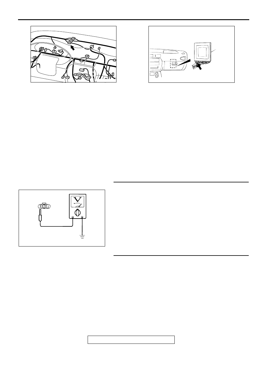
STEP 1. Check the circuit at fan controller connector A-30.
(1) Disconnect fan controller connector A-30, and measure at 

the harness side connector.

(2) Measure the voltage between terminal number 3 and 

ground.

When the ignition switch is turned to "ON" position, 
voltage should be battery positive voltage.

Q: Is the voltage battery positive voltage when the ignition 

switch is turned to "ON" position?
YES : 
Go to Step 7.
NO :  Go to Step 2.

STEP 2. Check the fan control relay.
Refer to 

P.14-15

.

Q: Is the fan control relay in good condition?

YES : Go to Step 3.
NO :  Replace it, then go to Step 10.

AC004036AB

CONNECTOR: C-04

AC004037AB

CONNECTOR: C-39

PCM

AC000246

CONNECTOR A-30

AB

ENGINE COOLING DIAGNOSIS

TSB Revision

ENGINE COOLING

14-7

STEP 3. Check for continuity between fusible link number 
5 and fan control relay connector A-13X.
Q: Are the harness wires between fusible link number 5 

and fan control relay connector A-13X damaged? 
YES : 
Repair or replace them, then go to Step 12.
NO :  Go to Step 4.

STEP 4. Check for continuity between fan control relay 
connector A-13X and fan controller connector A-30.
Q: Are the harness wires between fan control relay 

connector A-13X and fan controller connector A-30 
damaged?
YES : 
Repair or replace them, then go to Step 12
NO :  Go to Step 5.

STEP 5. Check for continuity between MFI relay connector 
A-21X and fan control relay connector A-13X.
Q: Are the harness wires between MFI relay connector A-

21X and fan control relay connector A-13X damaged?
YES : 
Repair or replace them, then go to Step 12.
NO :  Go to Step 6.

AC000247AC

BATTERY

FUSIBLE LINK (4) AND
CONNECTOR: A-13X

A-13X

FUSIBLE
LINK (4)

AC000248AB

CONNECTOR: A-13X

BATTERY

AC000270 AB

CONNECTOR: A-30

RADIATOR
FAN

AC000250

BATTERY

CONNECTORS: A-13X, A-21X

A-13X

A-21X

AB

ENGINE COOLING DIAGNOSIS

TSB Revision

ENGINE COOLING

14-8

STEP 6. Check for continuity between fan control relay 
connector A-13X and ground.
Q: Are the harness wires between fan control relay 

connector A-13X and ground damaged?
YES : 
Repair or replace them, then go to Step 12.
NO :  There is no action to be taken.

STEP 7. Check the circuit at fan controller connector A-30.
(1) Disconnect fan controller connector A-30, and measure at 

the harness side connector.

(2) Measure the resistance between terminal number 1 and 

ground.

Q: Is the resistance less than 2 ohm?

YES : Go to Step 9.
NO :  Go to Step 8.

STEP 8. Check the harness wire between fan controller 
connector A-30 and ground.
Q: Are the harness wires between fan controller connector 

A-30 and ground damaged?
YES : 
Repair or replace them, then go to Step 12.
NO :  There is no action to be taken.

STEP 9. Check the circuit at PCM connector C-39.
(1) Connect PCM connector C-39.
(2) Start the engine and allow it to idle.
(3) Measure the voltage between terminal number 18 and 

ground.

Q: Is the voltage 0.7 volt or more when the radiator fan is 

operating?
YES : 
Go to Step 11.
NO :  Go to Step 10.

AC000248AB

CONNECTOR: A-13X

BATTERY

AC000252 AB

CONNECTOR: A-30

AC000270 AB

CONNECTOR: A-30

RADIATOR
FAN

AC004039 AB

CONNECTOR 
C-39

ENGINE COOLING DIAGNOSIS

TSB Revision

ENGINE COOLING

14-9

STEP 10. Check the harness wire between PCM connector 
C-39 and fan controller connector A-30.
NOTE: If intermediate connector C-04 is damaged, repair or 
replace it. Refer to GROUP 00E, Harness Connector 
Inspection

P.00E-2

.

Q: Are the harness wires between PCM connector C-39 and 

fan controller connector A-30 damaged?
YES : 
Repair or replace them, then go to Step 12.
NO :  Go to Step 11.

STEP 11. Check the fan controller at PCM connector C-39.
(1) Disconnect PCM connector C-39.
(2) Pull out pin 18 to disconnect it.
(3) Reconnect PCM connector C-39 with pin 18 still removed.
(4) Turn the ignition switch to "ON" position.

Q: Do the radiator fan motor and condenser fan motor 

operate?
YES : 
Replace the PCM. Then go to Step 12.
NO :  Replace the radiator fan motor and fan controller 

assembly.Then go to Step 12    .

AC004036AB

CONNECTOR: C-04

AC004037AB

CONNECTOR: C-39

PCM

AC000270 AB

CONNECTOR: A-30

RADIATOR
FAN

AC004040AB

CONNECTOR C-39


Content   ..  330  331  332  333   ..