Mitsubishi Galant. Manual - part 326


  Index      Mitsubishi     Mitsubishi Galant - service repair manual 2001 year


Search            


Content   ..  324  325  326  327   ..


Mitsubishi Galant. Manual - part 326


THROTTLE BODY ASSEMBLY

TSB Revision

MULTIPORT FUEL INJECTION (MFI) <3.0L>

13B-529

3. If it dose not turn smoothly, the O-ring may be trapped, 

remove the item, re-install it into the fuel rail and check 
again.

4. Tighten the fuel pressure regulator and high-pressure fuel 

hose to the specified torque.

Tightening torque:

8.8 N

⋅⋅⋅⋅

m (78 in-lb) <Fuel pressure regulator>

4.9 N

⋅⋅⋅⋅

m (43 in-lb) <High-pressure fuel hose>

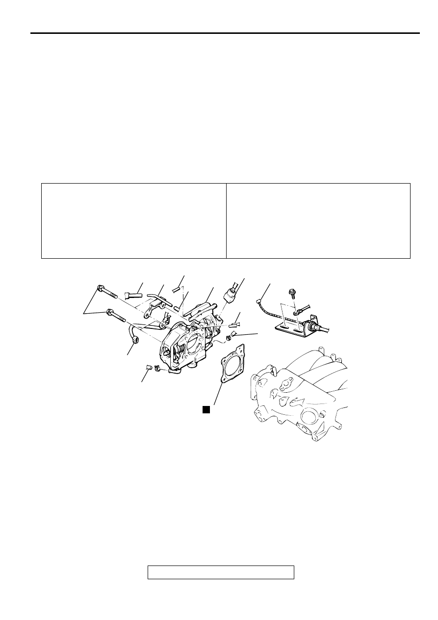
TH R O TTLE B O D Y A SSEM B LY

REMOVAL AND INSTALLATION

M1131007700102

Pre-removal Operation

Engine Coolant Draining [Refer to GROUP 00, 
Maintenance Service 

 Engine Coolant (Change)

P.00-

50

.]

Air Cleaner Removal (Refer to GROUP 15, Air 
Cleaner

P.15-4

.)

Post-installation Operation

Air Cleaner Installation (Refer to GROUP 15, Air 
Cleaner

P.15-4

.)

Engine Coolant Refilling [Refer to GROUP 00, 
Maintenance Service 

 Engine Coolant (Change)

P.00-

50

.]

Accelerator Cable Adjustment (Refer to GROUP 17, On-
vehicle Service 

 Accelerator Cable Check and 

Adjustment

P.17-4

.)

AC001624

4

6

4

4

7

2

1

4

3

5

5

8

19 N·m
14 ft-lb

AC

N

REMOVAL STEPS

1.

ACCELERATOR CABLE 
CONNECTION

2.

THROTTLE POSITION SENSOR 
CONNECTOR

3.

IDLE AIR CONTROL MOTOR 
CONNECTOR

4.

VACUUM HOSE CONNECTION

5.

WATER HOSE CONNECTION

6.

VACUUM PIPE CONNECTION

7.

THROTTLE BODY

>>A<<

8.

THROTTLE BODY GASKET

REMOVAL STEPS (Continued)

THROTTLE BODY ASSEMBLY

TSB Revision

MULTIPORT FUEL INJECTION (MFI) <3.0L>

13B-530

INSTALLATION SERVICE POINT

>>A<<THROTTLE BODY GASKET INSTALLATION

CAUTION

Poor idling etc. may result if the throttle body gasket is 
installed incorrectly.
Install the throttle body gasket as shown in the illustration.

DISASSEMBLY AND ASSEMBLY

M1131009700119

AC000233

PROJECTION

AB

AK000588

6

8

7

5

9

2

1

4

3

4.9 N·m
43 in-lb

4.9 N·m
43 in-lb

6.9 N·m
61 in-lb

2.0 N·m
18 in-lb

4.9 N·m
43 in-lb

2.0 N·m
18 in-lb

2.0 N·m
18 in-lb

AC

REMOVAL STEPS

<<A>>

>>A<<

1. THROTTLE POSITION SENSOR
2. LEVER ASSEMBLY

3. IDLE AIR CONTROL MOTOR
4. O-RING

REMOVAL STEPS (Continued)

THROTTLE BODY ASSEMBLY

TSB Revision

MULTIPORT FUEL INJECTION (MFI) <3.0L>

13B-531

NOTE: IF THE ADJUSTING SCREW WAS HAPPEN 
TO HAVE BEEN REMOVED, PERFOM SPEED 
ADJUSTING SCREW ADJUSTMENT.

DISASSEMBLY SERVICE POINTS

<<A>>THROTTLE POSITION SENSOR DISASSEBLY
1. Do not disassemble the sensor and motor.

2. Do not clean the sensor and motor by dipping them into 

cleaning solvent. Clean them with shop towel.

<<B>>THROTTLE BODY DISASSEBLY
1. Do not disassemble the throttle body. 

2. Check if the vacuum port or passage is clogged. Use 

compressed air to clean the vacuum passage.

ASSEMBLY SERVICE POINTS

>>A<<THROTTLE POSITION SENSOR(TPS) INSTALLTION
1. Install the throttle position sensor to the throttle body as 

shown in the illustration.

2. Turn the throttle position sensor 90 degrees 

counterclockwise to set it, and tighten the screws.

<<B>>

5. THROTTLE BODY
6. THROTTLE SPEED ADJUSTING 

SCREW

7. BRACKET
8. SPEED ADJUSTING SCREW
9. O-RING

REMOVAL STEPS (Continued)

AK000037

TPS

AB

1 2 3 4

AK000038AB

SPECIFICATIONS

TSB Revision

MULTIPORT FUEL INJECTION (MFI) <3.0L>

13B-532

3. Connect an ohmmeter between terminals 1 (ground) and 3 

(output), or between terminals 3 (output) and 4 (power).
Then, make sure that the resistance changes smoothly 
when the throttle valve is slowly moved to the fully open 
position. 

INSPECTION

M1131009800053

DASH POT

1. Push the dash pot rod in lightly and confirm the resistance.

NOTE: Resistance increases as the rod is pushed harder.

NOTE: If the rod can be pushed in with no resistance, either 
the diaphragm or check valve is faulty.

2. Release finger and confirm that the rod returns to it's original 

position quickly.

NOTE: If the rod returns slowly, the check valve is faulty.

SPECIFIC ATIO NS

FASTENER TIGHTENING SPECIFICATIONS

M1131011600119

GENERAL SPECIFICATIONS

M1131000200087

AKX01635

THROTTLE POSITION 
SENSOR POWER

GROUND

THROTTLE POSITION 
SENSOR OUTPUT

AB

ITEM

SPECIFICATION

Fuel pressure regulator

8.8 N

m (78 in-lb)

Fuel rail mounting bolt

9.8 

 13 N

m (87 

 115 in-lb)

High-pressure fuel hose

4.9 N

m (43 in-lb)

Idle air control motor

2.0 N

m (18 in-lb)

Lever assembly

4.9 N

m (44 in-lb)

Throttle body bracket M6

4.9 N

m (44 in-lb)

Throttle body bracket M8

6.9 N

m (61 in-lb)

Throttle body to intake manifold bolt

19 N

m (14 ft-lb)

Throttle position sensor

2.0 N

m (18 in-lb)

Throttle speed adjusting screw mounting nut

2.0 N

m (18 in-lb)

ITEMS

SPECIFICATIONS

Throttle body

Throttle bore mm (in.)

60 (2.4)

Throttle position sensor

Variable resistor type

Idle air control motor

Stepper motor (stepper motor type by-
pass air control system with the air 
volume limiter)


Content   ..  324  325  326  327   ..