Mitsubishi Galant. Manual - part 322


  Index      Mitsubishi     Mitsubishi Galant - service repair manual 2001 year


Search            


Content   ..  320  321  322  323   ..


Mitsubishi Galant. Manual - part 322


MULTIPORT FUEL INJECTION(MFI) DIAGNOSIS

TSB Revision

MULTIPORT FUEL INJECTION (MFI) <3.0L>

13B-513

Measurement Method
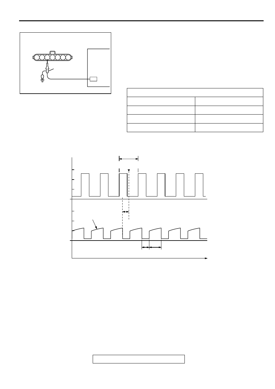
1. Disconnect the connector, and connect test harness special 

tool, (MB991348), in between. (All terminals should be 
connected.)

2. Connect the oscilloscope probe to ignition coil connector 

terminal 3.

Alternate method (Test harness not available)

1. Connect the oscilloscope probe to PCM terminal 11.

Standard Wave Pattern

Wave Pattern Observation Points
Point: Condition of wave pattern build-up section and maximum 

voltage (Refer to abnormal wave pattern examples 1 and 2.

Observation conditions

Function

Special pattern

Pattern height

Low

Pattern selector

Display

Engine r/min

Approximately 1,200 r/min

AK000067

1 2 3 4 5 6 7

OSCILLOSCOPE

DISTRIBUTOR 
CONNECTOR

OSCILLO

SCOPE

PLOBE

AB

AK000069

CRANKSHAFT

POSITION

SENSOR OUTPUT

WAVE PATTERN

(REFERENCE)

IGNITION POWER

TRANSISTOR

CONTROL SIGNAL

WAVE PATTERN

POINT:

WAVE BUILD-UP

SECTION

Standard wave pattern

θ

θ 

: SPARK ADVANCE ANGLE

ON

DWELL SECTION

TIME

OFF

T

T : CRANKSHAFT ANGLE (120˚)

COMPRESSION
TOP DEAD CENTER

0

2

4

6

0

2

4

6

(V)

MULTIPORT FUEL INJECTION(MFI) DIAGNOSIS

TSB Revision

MULTIPORT FUEL INJECTION (MFI) <3.0L>

13B-514

Examples of Abnormal Wave Patterns
Example 1 (Wave pattern during engine cranking)

Cause of problem
Open-circuit in ignition primary circuit

Wave pattern characteristics
Top-right part of the build-up section cannot be seen, and 
voltage value is approximately 2 volts too low.

Example 2 (Wave pattern during engine cranking)

Cause of problem
Malfunction in ignition power transister

Wave pattern characteristics
Power voltage results when the ignition power transistor is 
ON.

CONDITION OF WAVE 
PATTERN BUILD-UP 
SECTION AND MAXIMUM 
VOLTAGE

PROBABLE CAUSE

Rises from approximate 2 
volts to approximate 4.5 volts 
at the top-right

Normal

2-volt rectangular wave

Open-circuit in ignition primary 
circuit

Rectangular wave at power 
voltage

Ignition power transistor 
malfunction

AKX01612

NORMAL WAVE
PATTERN

2V

AB

AKX01613

BATTERY
POSITION
VOLTAGE

NORMAL WAVE
PATTERN

AB

SPECIAL TOOLS

TSB Revision

MULTIPORT FUEL INJECTION (MFI) <3.0L>

13B-515

SPECIA L TO O LS

M1131000600096

TOOL

TOOL NUMBER AND 
NAME

SUPERSESSION

APPLICATION

MB991502
Scan tool <MUT-II>

MB991496-OD

Reading diagnostic 
trouble code

MFI system inspection

Measurement of fuel 
pressure

MB991348
Test harness set

MB991348-01

Adjustment of throttle 
position sensor

Inspection using an 
oscilloscope

MB991709
Test harness set

MB991709-01

Inspection using an 
oscilloscope

Inspection of idle air 
control motor

MB991658
Test harness set

Tool not available

Inspection of heated 
oxygen sensor

MD998464
Test harness (4 pin, 
square)

MD998464-01

Inspection of heated 
oxygen sensor

Inspection using an 
oscilloscope

MB991316
Test harness (4 pin, 
square)

Tool not available

Inspection of heated 
oxygen sensor

MD998478
Test harness (3 pin, 
triangle)

MD998478-01

Inspection using an 
oscilloscope

B991502

MB991348

MB991658

ON-VEHICLE SERVICE

TSB Revision

MULTIPORT FUEL INJECTION (MFI) <3.0L>

13B-516

O N -VEH IC LE SERVIC E

COMPONENT LOCATION

M1131002100097

MD998709
Adaptor hose

MIT210196

Measurement of fuel 
pressure

MD998742
Hose adaptor

MD998742-01

MB991637
Fuel pressure gauge set

Tool not available

TOOL

TOOL NUMBER AND 
NAME

SUPERSESSION

APPLICATION

MB991637

NAME

SYMBOL

NAME

SYMBOL

Air conditioning compressor clutch 
relay

J

Knock sensor

E

Crankshaft position sensor

KLeft bank heated oxygen sensor 

(front)

N

Data link connector

T

Left bank heated oxygen sensor 
(rear)

M

Distributor (built-in camshaft position 
sensor and ignition coil)

I

Manifold differential pressure sensor D

EGR solenoid

A

Multiport fuel injection (MFI) relay/
fuel pump relay

J

Engine coolant temperature sensor

P

Park/neutral position switch

Q

Evaporative emission purge 
solenoid

A

Powertrain control module

U

Evaporative emission ventilation 
solenoid

R

Power steering pressure switch

L

Fan controller

O

Right bank heated oxygen sensor 
(front)

B

Fuel tank differential pressure 
sensor

W

Right bank heated oxygen sensor 
(rear)

V


Content   ..  320  321  322  323   ..