Mitsubishi Galant. Manual - part 315


  Index      Mitsubishi     Mitsubishi Galant - service repair manual 2001 year


Search            


Content   ..  313  314  315  316   ..


Mitsubishi Galant. Manual - part 315


MULTIPORT FUEL INJECTION(MFI) DIAGNOSIS

TSB Revision

MULTIPORT FUEL INJECTION (MFI) <3.0L>

13B-485

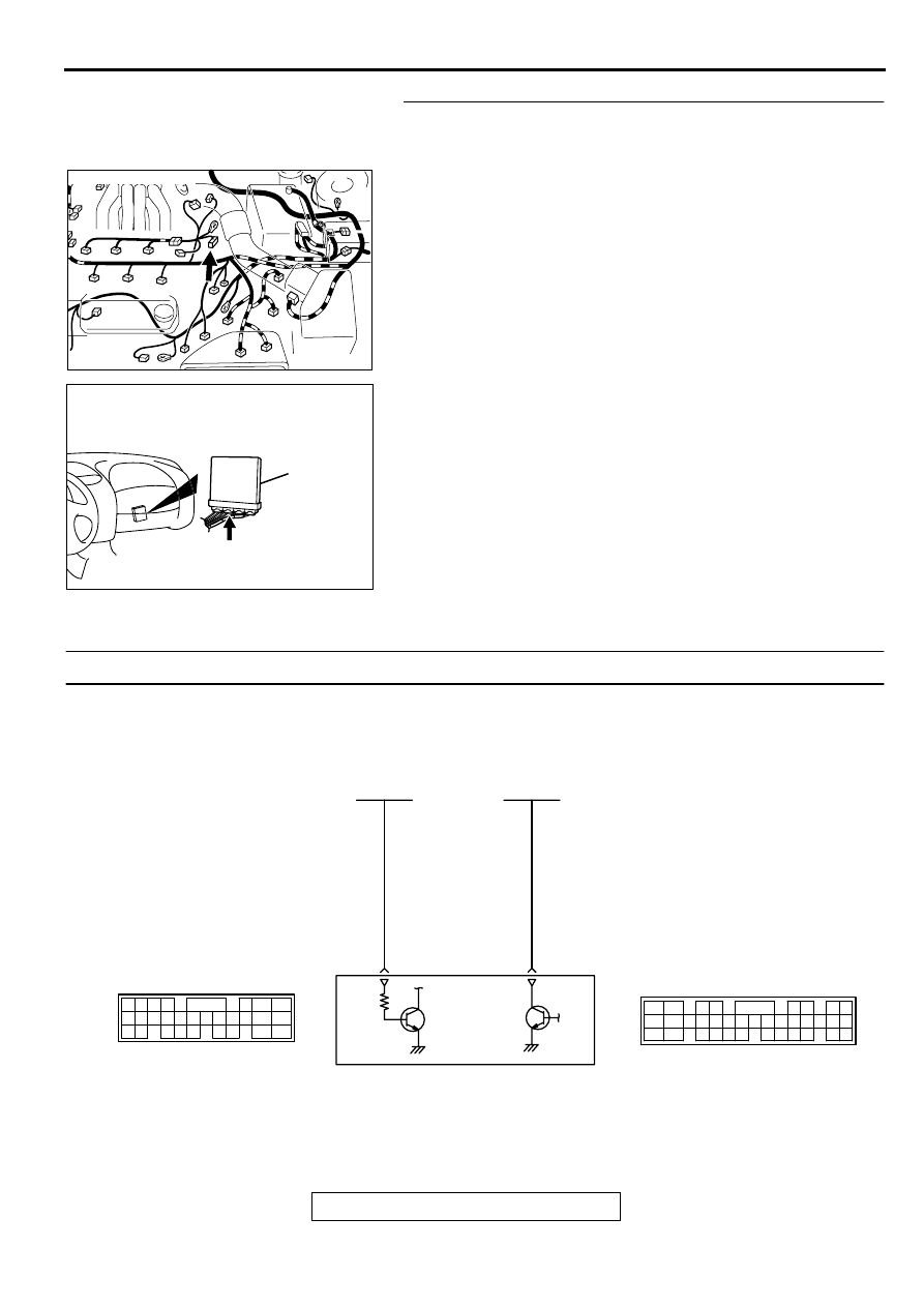
STEP 8. Check for open circuit between distributor 
connector B-27 terminal 2 and PCM connector C-40 
terminal 43.
Q: Is the harness wire in good condition?

YES : Replace the PCM. Then confirm that the malfunction 

symptom is eliminated.

NO :  Repair it. Then confirm that the malfunction symptom 

is eliminated.

INSPECTION PROCEDURE 33: A/C system.

AK000619 AD

CONNECTOR:B-27

AK000280

CONNECTOR : C-40

PCM

AV

AK000529

GREEN-RED

GREEN

POWERTRAIN CONTROL
MODULE(PCM)

83

20

A/C COMPRESSOR
RELAY

AUTOMATIC
COMPRESSOR
CONTROLLER

98

78

71

88 89

76 77

72
79
91

73
80

74

75

81
92

82 83
93

84 85

94

86 87

95 96

90

97

      C-41
(MU803782)

      C-39
(MU803784)

2

3 4

5 6

7 8

9

11 12 13 14 15 16 17 18 19 20

30

21 22 23

24 25

26 27 28 29

3132 33

34 35

1

10

MULTIPORT FUEL INJECTION(MFI) DIAGNOSIS

TSB Revision

MULTIPORT FUEL INJECTION (MFI) <3.0L>

13B-486

COMMENT

When the A/C is "ON," the battery positive 
voltage is applied on the PCM (terminal 83) from 
the automatic compressor controller. 
When battery positive voltage is applied to the 
PCM, the PCM turns "ON" the power transistor in 
the PCM. The PCM delays A/C engagement 
momentarily while it increases idle rpm. Then the 
A/C compressor clutch relay coil will be 
energized. 

With this, the A/C compressor clutch relay turns 
"ON," and the A/C compressor clutch functions.

TROUBLESHOOTING HINTS (The most likely 
causes for this case:)

Malfunction of the A/C control system.

Malfunction of the A/C switch.

Improper connector contact, open circuit or short-
circuited harness wire.

Malfunction of the PCM.

DIAGNOSIS

STEP 1. Check connector C-39, C-41 at PCM for damage.
Q: Is the connector in good condition?

YES : Go to Step 2.
NO :  Repair or replace it. Refer to GROUP 00E, Harness 

Connector Inspection (

P.00E-2

). Then confirm that 

the malfunction symptom is eliminated.

STEP 2. Check the circuit at PCM connector C-39.
(1) Disconnect the connectors C-39 and measure at the 

harness side.

(2) Turn the ignition switch to the "ON" position.
(3) Measure the voltage between terminal 20 and ground.

Voltage should be battery positive voltage.

(4) Using a jumper wire, connect terminal 20 to ground.

A/C compressor relay should turn "ON".

(5) Turn the ignition switch to the "LOCK" (OFF) position.

Q: Is the voltage and A/C compressor relay condition 

normal?
YES : 
Go to Step 3.
NO :  Refer to GROUP 55, Diagnosis 

 Introduction To 

Heater, Air Conditioning And Ventilation Diagnosis 
(

P.55-4

). Then confirm that the malfunction symptom 

is eliminated.

AK000280

CONNECTORS : C-39, C-41

C-39

C-41

PCM

AZ

AK000280

CONNECTORS : C-39, C-41

C-39

C-41

PCM

AZ

AKX01448

C-39   HARNESS
SIDE  CONNECTOR

8 7

6 5

4 3

2

1
9

10

11

12

13

14

15

16

17

18

19

20

21

22

23
3534

3332 3130

29282726

25 24

AE

MULTIPORT FUEL INJECTION(MFI) DIAGNOSIS

TSB Revision

MULTIPORT FUEL INJECTION (MFI) <3.0L>

13B-487

STEP 3. Check the circuit at PCM connector C-41.
(1) Disconnect the connectors C-41 and measure at the 

harness side.

(2) Turn the ignition switch to the "ON" position.
(3) Measure the voltage between terminal 83 and ground.

Voltage should be 1 volt or less when the A/C switch is 
"OFF".

Voltage should be battery positive voltage when the A/C 
switch is "ON".

(4) Turn the ignition switch to the "LOCK" (OFF) position.

Q: Is the voltage normal?

YES : Replace the PCM. Then confirm that the malfunction 

symptom is eliminated.

NO :  Refer to GROUP 55, Diagnosis 

 Introduction To 

Heater, Air Conditioning And Ventilation Diagnosis 
(

P.55-4

). 

DATA LIST REFERENCE TABLE

M1131008900110

CAUTION

When shifting the select lever to D range, the brakes should be applied so that the vehicle does 
not move forward.

Driving tests always need two persons: one driver and one observer.

NOTE: Sensor 1 indicates the sensor mounted at a position closest to the engine, and sensor 2 indicates the 
sensor mounted at the position second close to the engine.

NOTE: Bank 1 indicates the right bank cylinder, and bank 2 indicates the left bank cylinder.

NOTE: 

*1: 

If the idle speed is lower than the standard value on a very cold engine (approximately -20

°

C

 (

-4

°

F) 

even when the IAC motor is fully opened, the air volume limiter built in the throttle body could be defective.

NOTE: 

*2: 

 In a new vehicle [driven approximately 500 km (311 mile) or less], the step of the stepper motor is 

sometimes 30 steps greater than the standard value.

NOTE: 

*3: 

The injector drive time represents the time when the cranking speed is at 250 r/min or below when 

the power supply voltage is 11 volts.

NOTE: 

*4: 

 In a new vehicle [driven approximately 500 km (311 mile) or less], the injector drive time  is 

sometimes 10% longer than the standard time.

NOTE: 

*5

: In a new vehicle [driven approximately 500 km (311 mile) or less], the volume air flow sensor 

output frequency is sometimes 10% higher than the standard frequency.

NOTE: 

*6

: Applicable to GST

AKX01449

71

72

73

74

75

76

77
89 88 87 86 858483 82 8180 7978

90

91

92

93

94

95

96

97

98

C-41   HARNESS
SIDE  CONNECTOR

AE

MULTIPORT FUEL INJECTION(MFI) DIAGNOSIS

TSB Revision

MULTIPORT FUEL INJECTION (MFI) <3.0L>

13B-488

MUT-II 
SCAN 
TOOL 
DISPLAY

ITEM 
NO. 

INSPECTION 
ITEM

INSPECTION REQUIREMENT

NORMAL 
CONDITION

INSPECTION 
PROCEDURE 
NO.

REFER
ENCE 
PAGE

A/C 
RELAY

49

A/C 
compressor 
clutch relay

Engine: 
warming up, 
idling

A/C switch: 
"OFF"

OFF 
(Compressor 
clutch is not 
operating)

Procedure 
No.33

P.13B-
485

A/C switch: 
"ON"

ON 
(Compressor 
clutch is 
operating)

A/C 
SWITCH

28

A/C switch

Engine: idling 
(when A/C 
switch is ON, 
A/C 
compressor 
should be 
operating)

A/C 
switch:"OFF"

OFF

Procedure 
No.33

P.13B-
485

A/C 
switch:"ON"

ON

BARO 
SENSOR

25

Barometric 
pressure 
sensor

Ignition switch: 
"ON"

At altitude of  0 
m (0 ft)

101 kPa

Code 
No.P0107,
P0108

P.13B-
40

,

P.13

B-49

At altitude of  
600 m (1,969 
ft)

95 kPa

At altitude of  
1,200 m (3,937 
ft)

88 kPa

At altitude of  
1,800 m (5,906 
ft)

81 kPa

BATT 
VOLTAGE

16

power supply 
voltage

Ignition switch: "ON"

Battery positive 
voltage

Procedure 
No.29

P.13B-
466


Content   ..  313  314  315  316   ..