Mitsubishi Galant. Manual - part 293


  Index      Mitsubishi     Mitsubishi Galant - service repair manual 2001 year


Search            


Content   ..  291  292  293  294   ..


Mitsubishi Galant. Manual - part 293


MULTIPORT FUEL INJECTION(MFI) DIAGNOSIS

TSB Revision

MULTIPORT FUEL INJECTION (MFI) <3.0L>

13B-397

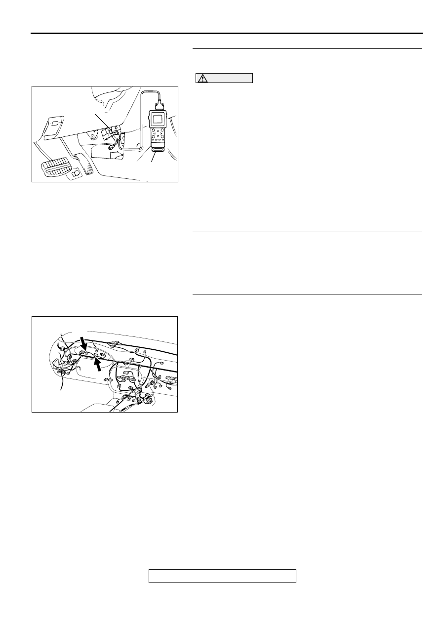
STEP 1. Using scan tool MB991502, check data list item 16: 
Power Supply Voltage.

CAUTION

To prevent damage to scan tool MB991502, always turn the 
ignition switch to the "LOCK" (OFF) position before. 
connecting or disconnecting scan tool MB991502.
(1)  Connect scan tool MB991502 to the data link connector.
(2)  Turn the ignition switch to the "ON" position.
(3) Set scan tool MB991502 to the data reading mode for   item 

16, Power Supply Voltage.

Voltage should be battery positive voltage.

(4) Turn the ignition switch to the "LOCK" (OFF) position.

Q: Is the voltage normal?

YES : Go to Step 2.
NO :  Refer to INSPECTION PROCEDURE 29 

 Power 

Supply System and Ignition Switch-IG System(

P.13B-

466

).

STEP 2. Check the burned-out bulb.

Q: Is the valve normal?

YES :  Go to step 3.
NO :   Replace the bulb. Then confirm that the malfunction 

symptom is eliminated.

STEP 3. Check connector C-29,C-30 at the combination 
meter for damage.
Q: Is the connector in good condition?

YES :  Go to step 4.
NO :  Repair or replace it. Refer to GROUP 00E, Harness 

Connector Inspection(

P.00E-2

). Then confirm that the 

malfunction symptom is eliminated.

AC003081 AB

16 PIN

MB991502

AK000633

C-29

C-30

CONNECTORS:C-29,C-30

AG

MULTIPORT FUEL INJECTION(MFI) DIAGNOSIS

TSB Revision

MULTIPORT FUEL INJECTION (MFI) <3.0L>

13B-398

STEP 4. Check the power supply voltage at combination 
meter harness side connector C-29.
(1) Disconnect the connector C-29 and measure at the harness 

side.

(2) Turn the ignition switch to the "ON" position.
(3) Measure the voltage between terminal 29 and ground.

Voltage should be battery positive voltage.

(4)  Turn the ignition switch to the "LOCK" (OFF) position.

Q: Is the voltage normal?

YES : Go to Step 5.
NO :  Check harness connectors C-73 and C-78 at 

intermediate connector for damage, and repair or 
replace as required. Refer to GROUP 00E, Harness 
Connector Inspection(

P.00E-2

). If intermediate 

connectors are in good condition, repair harness wire 
between ignition switch connector C-58 terminal 2 
and combination meter connector C-29 terminal 29 
because of open circuit. Then confirm that the 
malfunction symptom is eliminated.

STEP 5. Check connector C-39 at PCM for damage.
Q: Is the connector in good condition?

YES :  Go to Step 6.
NO :   Repair or replace it. Refer to GROUP 00E, Harness 

Connector Inspection(

P.00E-2

). Then confirm that the 

malfunction symptom is eliminated.

AK000635

C-29   HARNESS
SIDE  CONNECTOR

36 35 3433 32 31302928

27 26252423 22 21

AB

AK000280

CONNECTOR : C-39

PCM

AW

MULTIPORT FUEL INJECTION(MFI) DIAGNOSIS

TSB Revision

MULTIPORT FUEL INJECTION (MFI) <3.0L>

13B-399

STEP 6. Check the power supply voltage PCM connector 
C-39.
(1) Disconnect the connector C-39 and measure at the harness 

side.

(2) Turn the ignition switch to the "ON" position.
(3) Measure the voltage between terminal 22 and ground.

 Voltage should be battery positive voltage.

(4) Turn the ignition switch to the "LOCK" (OFF) position.

Q: Is the voltage normal?

YES : Replace the PCM. Then confirm that the malfunction 

symptom is eliminated.

NO :  Check harness connectors C-17 at intermediate 

connector for damage, and repair or replace as 
required. Refer to GROUP 00E, Harness Connector 
Inspection(

P.00E-2

). If intermediate connectors is in 

good condition, repair harness wire between 
combination meter connector C-30 terminal 6 and 
PCM connector C-39 terminal 22 because of open 
circuit. Then confirm that the malfunction symptom is 
eliminated.

AK000377

8 7

6 5

4 3

2

1
9

10

11

12

13

14

15

16

17

18

19

20

21

22

23
35 34

33 32 3130

2928 27 26

25 24

C-39   HARNESS
SIDE  CONNECTOR

AC

MULTIPORT FUEL INJECTION(MFI) DIAGNOSIS

TSB Revision

MULTIPORT FUEL INJECTION (MFI) <3.0L>

13B-400

INSPECTION PROCEDURE 4: The Service Engine Soon/Malfunction Indicator Lamp Remains 
Illuminated and Never Goes Out.

AK000521

3

2

4 5 6

1 2 3
4 5 6

BLA

CK-

WHITE

1

BR

O

WN-

BLA

CK

BR

O

WN-

BLA

CK

BLA

CK-

WHITE

R

IG2

ST

LOCK

ACC

IG1

    C-73
MU801331

IGNITION
SWITCH

C-58

2

6

6

JUNCTION
BLOCK

29

6

SERVICE ENGINE SOON/
MALFUNCTION INDICATOR LAMP

POWERTRAIN CONTROL
MODULE(PCM)

21

22

     C-78
MU803457

1

6

4

5

11

10

12 13

15

17

16

14

19

18

8 9

7

20

2 3

C-17

7 8

5

3 4

35

34

10 11 12

2122 23 24

13 14 15

25 26 27

16

28

17

18 19 20

29

30 31

32 33

36 37

38

9

1 2

6

      C-39
(MU803784)

2

3 4

5 6

7 8

9

11 12 13 14 15 16 17 18 19 20

30

21 22 23

24 25

26 27 28 29

3132 33

34 35

1

10

24 25

21

26 27

22 23

29 30 3132

28

35 36

34

33

C-29

4 5

1

6 7

2 3

10 1112

9

15 16

14

13

C-30

8


Content   ..  291  292  293  294   ..