Mitsubishi Galant. Manual - part 282


  Index      Mitsubishi     Mitsubishi Galant - service repair manual 2001 year


Search            


Content   ..  280  281  282  283   ..


Mitsubishi Galant. Manual - part 282


MULTIPORT FUEL INJECTION(MFI) DIAGNOSIS

TSB Revision

MULTIPORT FUEL INJECTION (MFI) <3.0L>

13B-353

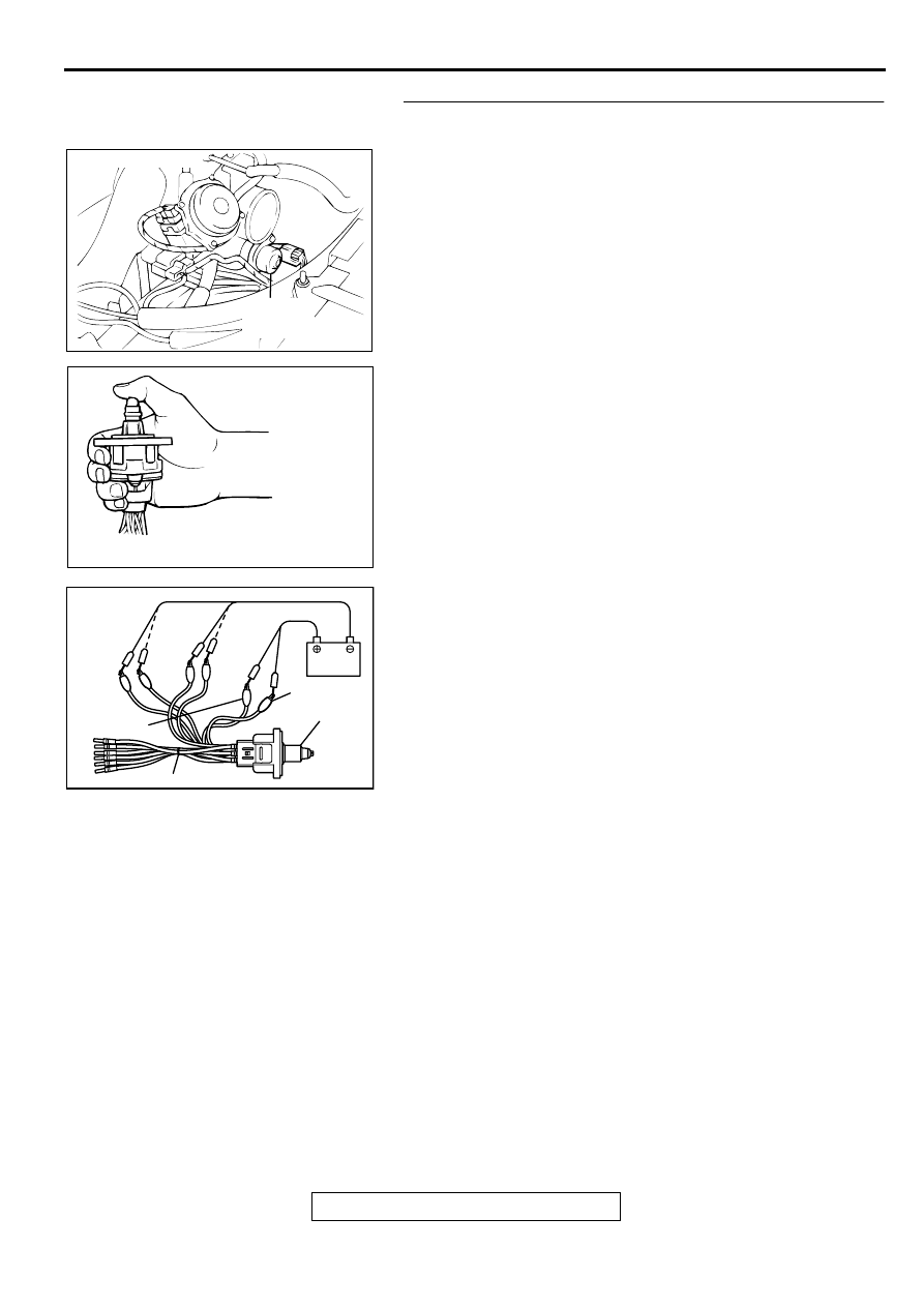
STEP 11. Check the idle air control motor operation using 
special tool MB991709.
(1) Remove the idle air control motor.
(2) Connect special tool MB991709 to the idle air control motor. 

(All terminals should be connected.)

(3) Use the jumper wires to connect terminal 2 of the idle air 

control motor connector to the battery (+) terminal.

(4) Check the ensure that the motor operates when the 

terminals 1 and 3 of the idle air control motor connector are 
respectively connected to the battery (-) terminal using a 
jumper wire.

Vibration should be present at each application of 
voltage to test clip combination.

(5) Then. Use jumper wires to connect the terminal 5 of the idle 

air control motor connector to the battery (+) terminal.

(6) Check the ensure that the motor operates when the 

terminals 4 and 6 of the idle air control motor connector are 
respectively connected to the battery (-) terminal using a 
jumper wire.

Vibration should be present at each application of 
voltage to test clip combination.

(7) Install the idle air control motor. Refer to, Throttle Body 


Disassembly and Assembly(

P.13B-530

).

Q: Is the idle air control motor operating properly?

YES : Go to Step 12.
NO :  Replace the idle air control motor. Then go to Step 14. 

ACX02523AG

IDLE AIR
CONTROL
MOTOR

CONNECTOR:B-06

AKX01626

AKX01627AB

TERMINAL 2

IAC MOTOR

TERMINAL 5

MB991709

MULTIPORT FUEL INJECTION(MFI) DIAGNOSIS

TSB Revision

MULTIPORT FUEL INJECTION (MFI) <3.0L>

13B-354

STEP 12. Check for harness damage between MFI relay 
connector A-21X terminal 1 and idle air control motor 
connector B-06 terminal 2, 5.
Q: Is the harness wire in good condition?

YES : Go to Step 13.
NO :  Repair it. Then go to Step 14.

STEP 13. Check for harness damage between idle air 
control motor connector B-06 and PCM connector C-39.

a. Idle air control motor connector B-06 terminal 1 and PCM 

connector C-39 terminal 14.

b. Idle air control motor connector B-06 terminal 3 and PCM 

connector C-39 terminal 28.

c. Idle air control motor connector B-06 terminal 4 and PCM 

connector C-39 terminal 15.

d. Idle air control motor connector B-06 terminal 6 and PCM 

connector C-39 terminal 29.

Q: Is the harness wire in good condition?

YES : Replace the PCM. Then go to Step 14.
NO :  Repair it. Then go to Step 14.

AK000555AB

CONNECTOR : A-21X

MFI RELAY

ACX02523AG

IDLE AIR
CONTROL
MOTOR

CONNECTOR:B-06

ACX02523AG

IDLE AIR
CONTROL
MOTOR

CONNECTOR:B-06

AK000280

CONNECTOR : C-39

PCM

AW

MULTIPORT FUEL INJECTION(MFI) DIAGNOSIS

TSB Revision

MULTIPORT FUEL INJECTION (MFI) <3.0L>

13B-355

STEP 14. Test the OBD-II drive cycle.
(1) Carry out a test drive with the drive cycle pattern. Refer to, 

Procedure 6 

 Other Monitor(

P.13B-4

).

(2) Check the diagnostic trouble code (DTC).

Q: Is the DTC P0507 is output?

YES : Retry the troubleshooting.
NO :  The inspection is complete.

DTC P0551: Power Steering Pressure Sensor Circuit Range/Performance

AK000516

1

YELLO

W

1

YELLO

W

POWERTRAIN CONTROL
MODULE(PCM)

POWER STEERING
PRESSURE SWITCH

B-44

1

52

     B-24
MU802653

1

      C-40
(MU803781)

42 43
48 49 50 51 52 53 54 55 56 57

46

45

44

58 59

60 61 62 63

64 65 66

47

41

ACX02522

CONNECTOR:B-44

POWER
STEERING
PRESSURE
SWITCH

AF

AK000617

CONNECTOR:B-44

AE

MULTIPORT FUEL INJECTION(MFI) DIAGNOSIS

TSB Revision

MULTIPORT FUEL INJECTION (MFI) <3.0L>

13B-356

CIRCUIT OPERATION

A battery positive voltage is applied to the power 
steering pressure switch output terminal (terminal 
1) from the PCM (terminal 52) via the resistor in 
the PCM.

TECHNICAL DESCRIPTION

The power steering pressure switch converts the 
existence of a power steering load into a high/low 
voltage, and inputs it into the PCM.

When the steering wheel is turned, hydraulic 
pressure rises. The power steering pressure 
switch closes, and the applied battery positive 
voltage will be grounded. With this, the power 
steering pressure switch output voltage will 
fluctuate between 12 volts and 0 volt.

While driving with the steering wheel held 
straight, the power steering pressure switch turns 
"OFF."

The PCM checks whether the power steering 
pressure switch turns "OFF" or "ON" during 
driving.

DTC SET CONDITIONS

Check Conditions

Intake air temperature is higher than -10

° 

C (14

° 

F).

Barometric pressure is higher than 76 kPa (11 
psi).

Engine coolant temperature is higher than 30

°

 C 

(86

°

 F).

Drive for four seconds or more with the engine 
speed at 2,500 r/min or more, the volumetric 
efficiency at 55 percent or more, and vehicle 
speed is 5 km/h (3.1 mph) or more. Stop the 
vehicle [vehicle speed is 1.5 km/h (0.93 mph) or 
less]. Repeat 10 times or more.

Judgment Criteria

Power steering pressure switch continues to be 
"ON."

TROUBLESHOOTING HINTS (The most likely 
causes for this code to be set are:)

Power steering pressure switch failed.

Open or shorted power steering pressure switch 
circuit, or loose connector.

PCM failed.

DIAGNOSIS

Required Special Tools
MB991502: Scan Tool (MUT-II)

AK000280

CONNECTOR : C-40

PCM

AV


Content   ..  280  281  282  283   ..