Mitsubishi Galant. Manual - part 268


  Index      Mitsubishi     Mitsubishi Galant - service repair manual 2001 year


Search            


Content   ..  266  267  268  269   ..


Mitsubishi Galant. Manual - part 268


MULTIPORT FUEL INJECTION(MFI) DIAGNOSIS

TSB Revision

MULTIPORT FUEL INJECTION (MFI) <3.0L>

13B-297

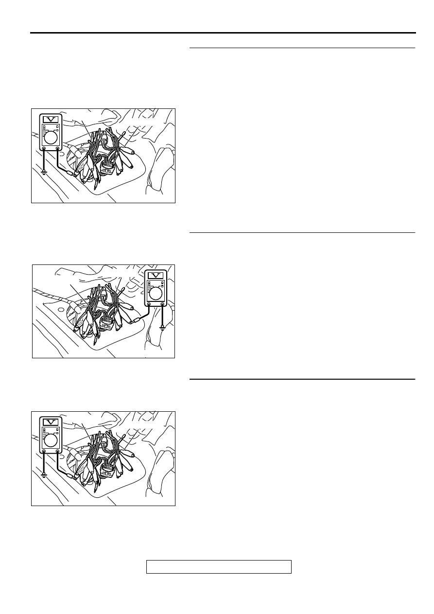
STEP 2. Check the output circuit voltage at intermediate 
connector D-15. 
(1) Remove the rear seat cushion. (Refer to GROUP 52A, Rear 

Seat

P.52A-20

.)

(2) Remove the protector.
(3) Do not disconnect intermediate connector D-15.
(4) Use special tools (MB991658 and MB991709) to connect 

terminals 5, 6 and 8 between connectors of the 
intermediate connector, respectively.

(5) Turn the ignition switch to the "ON" position.
(6) Remove the fuel cap.
(7) Measure the voltage between terminal 5 and ground by 

backprobing.

Voltage should be between 2.0 and 3.0 volts.

(8) Turn the ignition switch to the "LOCK" (OFF) position.

Q: Is the multi-meter reading within the specified value?

YES : Go to Step 10.
NO :  Go to Step 3.

STEP 3. Check the 5-volt supply circuit voltage at 
intermediate connector D-15.
(1) Do not disconnect intermediate connector D-15.
(2) Use special tools (MB991658 and MB991709) to connect 

terminals 5, 6 and 8 between connectors of the 
intermediate connector, respectively.

(3) Turn the ignition switch to the "ON" position.
(4) Measure the voltage between terminal 8 and ground by 

backprobing.

Voltage should be between 4.8 and 5.2 volts.

(5) Turn the ignition switch to the "LOCK" (OFF) position.

Q: Is the multi-meter reading within the specified value?

YES : Go to Step 4.
NO :  Go to Step 11.

STEP 4. Check the ground circuit voltage at intermediate 
connector D-15. 
(1) Do not disconnect intermediate connector D-15.
(2) Use special tools (MB991658 and MB991709) to connect 

terminals 5, 6 and 8 between connectors of the 
intermediate connector, respectively.

(3) Turn the ignition switch to the "ON" position.
(4) Measure the voltage between terminal 6 and ground by 

backprobing.

Voltage should be between 0.5 volts or less.

(5) Turn the ignition switch to the "LOCK" (OFF) position.

Q: Is the multi-meter reading within the specified value?

YES : Go to Step 5.
NO :  Go to Step 15.

AC002079 AB

MB991709

MB991658

AC002080

MB991709

MB991658

AB

AC002079 AB

MB991709

MB991658

MULTIPORT FUEL INJECTION(MFI) DIAGNOSIS

TSB Revision

MULTIPORT FUEL INJECTION (MFI) <3.0L>

13B-298

STEP 5. Check the output circuit voltage at fuel tank 
differential pressure connector D-11. 
(1) Remove the center pipe.
(2) Remove the fuel band assembly, tilt the fuel tank.
(3) Disconnect fuel tank differential pressure sensor connector 

D-11.

(4) Use special tool (MB991658) to connect terminals 1, 2 and 

3 of the disconnected sensor connector and those of the 
harness side connector, respectively.

(5) Turn the ignition switch to the "ON" position.
(6) Remove the fuel cap.
(7) Measure the voltage between terminal 1 and ground by 

backprobing.

Voltage should be between 2.0 and 3.0 volts.

(8) Turn the ignition switch to the "LOCK" (OFF) position.

Q: Is the multi-meter reading within the specified value?

YES : Go to Step 17.
NO :  Go to Step 6.

STEP 6. Check the 5-volt supply circuit voltage at fuel tank 
differential pressure sensor connector D-11.
(1) Do not disconnect fuel tank differential pressure sensor 

connector D-11.

(2) Use special tool (MB991658) to connect terminals 1, 2 and 

3 of the disconnected sensor connector and those of the 
harness side connector, respectively.

(3) Turn the ignition switch to the "ON" position.
(4) Measure the voltage between terminal 3 and ground by 

backprobing.

Voltage should be between 4.8 and 5.2 volts.

(5) Turn the ignition switch to the "LOCK" (OFF) position.

Q: Is the multi-meter reading within the specified value?

YES : Go to Step 7.
NO :  Go to Step 17.

STEP 7. Check the ground circuit voltage at fuel tank 
differential pressure sensor connector D-11. 
(1) Disconnect fuel tank differential pressure sensor connector 

D-11.

(2) Use special tool (MB991658) to connect terminals 1, 2 and 

3 of the disconnected sensor connector and those of the 
harness side connector, respectively.

(3) Turn the ignition switch to the "ON" position.
(4) Measure the voltage between terminal 2 and ground by 

backprobing.

Voltage should be between 0.5 volts or less.

(5) Turn the ignition switch to the "LOCK" (OFF) position.

Q: Is the multi-meter reading within the specified value?

YES : Go to Step 8.
NO :  Go to Step 17.

AC002081AB

MB991658

FUEL TANK DIFFERENTIAL 
PRESSURE SENSOR

AC002081AB

MB991658

FUEL TANK DIFFERENTIAL 
PRESSURE SENSOR

AC002081AB

MB991658

FUEL TANK DIFFERENTIAL 
PRESSURE SENSOR

MULTIPORT FUEL INJECTION(MFI) DIAGNOSIS

TSB Revision

MULTIPORT FUEL INJECTION (MFI) <3.0L>

13B-299

STEP 8. Check fuel tank differential pressure sensor 
connector D-11 for damage.
(1) Disconnect fuel tank differential pressure sensor connector 

D-11.

Q: Is there any failure at fuel tank differential pressure 

sensor connector D-11?
YES : 
Go to Step 9.
NO :  Repair or replace it. Refer to GROUP 00E, Harness 

Connector Inspection

P.00E-2

. Then go to Step 26.

STEP 9. Check the output voltage at fuel tank differential 
pressure sensor connector D-11. 
(1) Disconnect fuel tank differential pressure sensor connector 

D-11.

(2) Use special tool (MB991658) to connect terminals 2 and 3 

of the disconnected sensor connector and those of the 
harness side connector, respectively.

(3) Turn the ignition switch to the "ON" position.
(4) Remove the fuel cap.
(5) Measure the voltage between terminal 1 and ground by 

backprobing.

Voltage should be between 2.0 and 3.0 volts.

(6) Turn the ignition switch to the "LOCK" (OFF) position.

Q: Is the multi-meter reading within the specified value?

YES : Check connectors D-15, C-71, C-17, C-41 and repair 

or replace as required. Refer to GROUP 00E, 
Harness Connector Inspection

P.00E-2

. If connectors 

D-15, C-71, C-17, C-41 are in good condition, check 
the harness between fuel tank differential pressure 
sensor connector D-11 and PCM connector C-41 for 
short circuit to ground, then repair if necessary. Then 
go to Step 26.

NO :  Replace the fuel tank differential pressure sensor. 

Then go to Step 26. 

AC002041AC

CONNECTOR: D-11

FUEL TANK DIFFERENTIAL 
PRESSURE SENSOR

ACX01760AB

MB991658

FUEL TANK DIFFERENTIAL

PRESSURE SENSOR

MULTIPORT FUEL INJECTION(MFI) DIAGNOSIS

TSB Revision

MULTIPORT FUEL INJECTION (MFI) <3.0L>

13B-300

STEP 10. Check the output circuit voltage at PCM 
connector C-41. 
(1) Do not disconnect the PCM connector C-41.
(2) Turn the ignition switch to the "ON" position.
(3) Remove the fuel cap.
(4) Measure the voltage between terminal 92 and ground by 

backprobing.

Voltage should be between 2.0 and 3.0 volts.

(5) Turn the ignition switch to the "LOCK" (OFF) position.

Q: Is the multi-meter reading within the specified value?

YES : Go to Step 18.
NO :  Check connectors D-15, C-71, C-17, C-41 and repair 

or replace as required. Refer to GROUP00E, Harness 
Connector Inspection

P.00E-2

. If connectors D-15, C-

71, C-17, C-41 are in good condition, check the 
harness between intermediate connector D-15 and 
PCM connector C-41 for open circuit or damage. 
Then repair if necessary. Then go to Step 26.

STEP 11. Check the 5-volt supply circuit voltage at PCM 
connector C-40.
(1) Do not disconnect PCM connector C-40.
(2) Turn the ignition switch to the "ON" position.
(3) Measure the voltage between terminal 46 and ground by 

backprobing.

Voltage should be between 4.8 and 5.2 volts.

(4) Turn the ignition switch to the "LOCK" (OFF) position.

Q: Is the multi-meter reading within the specified value?

YES : Check connectors D-15, C-71, C-17, C-40 and repair 

or replace as required. Refer to GROUP 00E, 
Harness Connector Inspection

P.00E-2

. If connectors 

D-15, C-71, C-17, C-40 are in good condition, check 
the harness between intermediate connector D-15 
and PCM connector C-40 for open circuit or damage. 
Then repair if necessary. Then go to Step 26  .

NO :  Go to Step 12.

STEP 12. Check PCM connector C-40 for damage.
(1) Disconnect PCM connector C-40.

Q: Is there any failure at PCM connector C-40?

YES : Repair or replace it. Refer to GROUP 00E, Harness 

Connector Inspection

P.00E-2

. Then go to Step 26.

NO :  Go to Step 13.

AC004962 AB

C-41

HARNESS SIDE 
CONNECTOR

AC004963AB

C-40

HARNESS SIDE 
CONNECTOR

AC005043

CONNECTOR : C-40

PCM

AC


Content   ..  266  267  268  269   ..