Mitsubishi Galant. Manual - part 198
MULTIPORT FUEL INJECTION(MFI) DIAGNOSIS
TSB Revision
MULTIPORT FUEL INJECTION (MFI) <3.0L>
13B-17
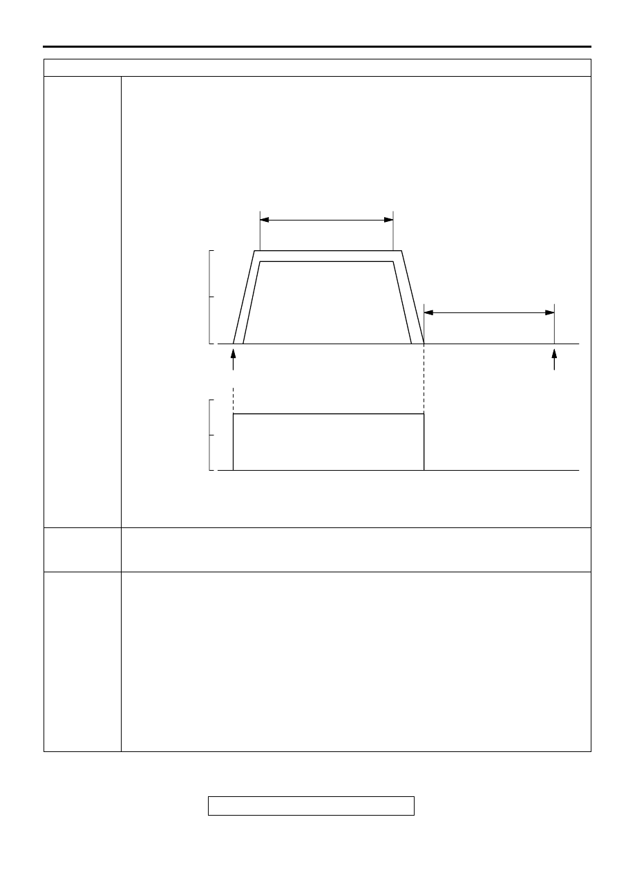
Drive cycle
pattern
This monitor [from start to ignition switch to the "LOCK" (OFF) position] will be completed
while traveling with the following drive cycle pattern. It will take 10 minutes. You must
complete this drive twice.
NOTE: . Drive according to the graph below.
Inspection
conditions
•
Engine coolant temperature: 80
°
C (176
°
F) or more
•
Atmospheric temperature: 5
°
C (41
°
F) or more
•
Condition of A/T: Selector lever D range
Test
procedure
Engine: start
Accelerate until the vehicle speed is 56
−
64 km/h (35
−
40 mph), and travel for 300 seconds
or more.
Return the vehicle to the shop.
After stopping the vehicle, continue idling for 300 seconds, and then turn the ignition switch
to the "LOCK" (OFF) position. Moreover, the vehicle should be set to the following
conditions for idling.
•
A/C switch: OFF
•
Lights and all accessories: OFF
•
Transaxle: P range
•
Steering wheel: Straightforward position
Confirm that the diagnostic trouble code (DTC) is not output.
If a DTC is output, refer to Diagnostic Trouble Code Chart.
OTHER MONITOR (Main components, sensors and switches, wire breakage and short circuit)
AKX01350
AKX01350
(3)
(2)
(1)
(4)
300 SECONDS OR MORE
56 - 64 km/h (35 - 40 mph)
ENGINE: IDLING
TRANSMISSION: NEUTRAL
300 SECONDS
ENGINE START
IGNITION
SWITCH:"LOCK"
(OFF)
64
(40)
32
(20)
0
100
50
0
VEHICLE
SPEED
km/h (mph)
<REFERENCE>
THROTTLE
OPENING
ANGLE (%)
AKX01350 AB