Mitsubishi Galant. Manual - part 186
MULTIPORT FUEL INJECTION(MFI) DIAGNOSIS
TSB Revision
MULTIPORT FUEL INJECTION (MFI) <2.4L>
13A-425
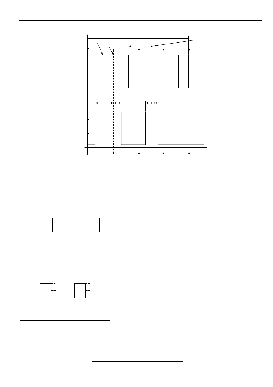
Wave Pattern Observation Points
Check that cycle time T becomes shorter when the engine
speed increased.
Examples of Abnormal Wave Patterns
Example 1
•
Cause of problem
Sensor interface malfunction.
•
Wave pattern characteristics
Rectangular wave pattern is output even when the engine is
not started.
Example 2
•
Cause of problem
Loose timing belt.
Abnormality in sensor disc.
•
Wave pattern characteristics
Wave pattern is displaced to the left or right.
AK000062
CYCLE TIME CHANGES
WITH ENGINE SPEED
CHANGES
2 ENGINE REVOLUTIONS (1 CAMSHAFT REVOLUTION)
75˚BTDC
142˚
58˚
63˚ 49˚
5˚BTDC
T
Standard wave pattern
CRANKSHAFT
POSITION
SENSOR OUTPUT
WAVE PATTERN
CAMSHAFT
POSITION
SENSOR OUTPUT
WAVE PATTERN
TIME
TDC: TOP DEAD CENTER
NO.1 TDC
NO.2 TDC
NO.3 TDC
NO.4 TDC
0
0
(V)
AB
AKX01597
AKX01602