Mitsubishi Galant. Manual - part 180


  Index      Mitsubishi     Mitsubishi Galant - service repair manual 2001 year


Search            


Content   ..  178  179  180  181   ..


Mitsubishi Galant. Manual - part 180


MULTIPORT FUEL INJECTION(MFI) DIAGNOSIS

TSB Revision

MULTIPORT FUEL INJECTION (MFI) <2.4L>

13A-401

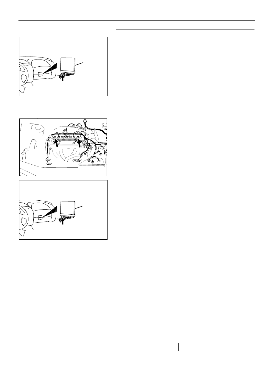
STEP 9. Check connector C-39 at PCM for damage.
Q: Is the connector in good condition?

YES : Go to Step 10.
NO :  Repair or replace it. Refer to GROUP 00E, Harness 

Connector Inspection(

P.00E-2

). Then confirm that the 

malfunction symptom is eliminated.

STEP 10. Check for open circuit between ignition coil 
connector and PCM connector.

a. Check the harness wire between ignition coil connector B-

09 terminal 3 and PCM connector C-39 terminal 11 when 
checking ignition coil 1.

b. Check the harness wire between ignition coil connector B-

23 terminal 3 and PCM connector C-39 terminal 12 when 
checking ignition coil 2.

Q: Is the harness wire in good condition?

YES : Replace the PCM. Then confirm that the malfunction 

symptom is eliminated.

NO :  Repair it. Then confirm that the malfunction symptom 

is eliminated.

AK000280

CONNECTOR : C-39

PCM

AW

AK000639AB

B-23

B-09

CONNECTORS:B-09,B-23

AK000280

CONNECTOR : C-39

PCM

AW

MULTIPORT FUEL INJECTION(MFI) DIAGNOSIS

TSB Revision

MULTIPORT FUEL INJECTION (MFI) <2.4L>

13A-402

STEP 11. Using the oscilloscope, check the ignition failure 
sensor.
(1) Disconnect the ignition failure sensor connector B-01, and 

connect test harness special tool (MB991658) in between. 
(All terminals should be connected.)

(2) Connect the oscilloscope probe to the ignition failure sensor 

side connector terminal 2.

(3) Start the engine and run at idle.
(4) Check the waveform.

The waveform should show a pattern similar to the 
illustration.

(5) Turn the ignition switch to the "LOCK"(OFF) position.

Q: Is the waveform normal?

YES : It can be assumed that this malfunction is intermittent. 

Refer to GROUP 00, How to Use Troubleshooting/
Inspection Service Points(

P.00-8

).

NO :  Go to Step 12.

STEP 12. Check the circuit at ignition failure sensor 
harness side connector B-01.
(1) Disconnect the connectors B-01 and measure at the 

harness side.

(2) Turn the ignition switch to the "ON" position.
(3) Measure the voltage between terminal 2 and ground.

Voltage should be 4 volts or more.

(4) Turn the ignition switch to the "LOCK"(OFF) position.

Q: Is the voltage normal?

YES : Repair harness wire between ignition failure sensor 

connector B-01 terminal 1 and ground because of 
open circuit or harness damage. Then confirm that 
the malfunction symptom is eliminated.

NO :  Go to Step 13.

STEP 13. Check connector C-40 at PCM for damage.
Q: Is the connector in good condition?

YES : Go to Step 14.
NO :  Repair or replace it. Refer to GROUP 00E, Harness 

Connector Inspection(

P.00E-2

). Then confirm that the 

malfunction symptom is eliminated.

AK000416 AB

OSCILLOSCOPE
PROBE

IGNITION FAILURE
SENSOR CONNECTOR

OSCILLOSCOPE

1 2 3 4

AK000417

NORMAL WAVEFORM (AT IDLING)

NOTE : CYCLE (T) SHORTENS AS
             THE ENGINE SPEED RISES.

AK000417AB

10V

T

AK000418

4 3 2 1

B-01   HARNESS
SIDE  CONNECTOR

AC

AK000280

CONNECTOR : C-40

PCM

AV

MULTIPORT FUEL INJECTION(MFI) DIAGNOSIS

TSB Revision

MULTIPORT FUEL INJECTION (MFI) <2.4L>

13A-403

STEP 14. Check for open circuit between ignition failure 
sensor connector B-01 terminal 2 and PCM connector C-40 
terminal 43.
Q: Is the harness wire in good condition?

YES : Replace the PCM. Then confirm that the malfunction 

symptom is eliminated.

NO :  Repair it. Then confirm that the malfunction symptom 

is eliminated.

INSPECTION PROCEDURE 33: A/C system.

ACX02471

CONNECTOR:B-01

IGNITION
FAILURE
SENSOR

AH

AK000280

CONNECTOR : C-40

PCM

AV

AK000486

GREEN-

RED

GREEN

POWERTRAIN CONTROL
MODULE(PCM)

83

20

      C-39
(MU803784)

      C-41
(MU803782)

A/C COMPRESSOR
RELAY

AUTOMATIC
COMPRESSOR
CONTROLLER

12

11

16

5 6

7 8

21

13
27

14
28

15
29

17
30

18
31

19
32

20
33

22
34

23
35

1

24

3

26

9

2

25

10

4

98

78

71

88 89

76 77

72
79
91

73
80

74

75

81
92

8283
93

8485

94

8687

9596

90

97

MULTIPORT FUEL INJECTION(MFI) DIAGNOSIS

TSB Revision

MULTIPORT FUEL INJECTION (MFI) <2.4L>

13A-404

COMMENT

When the A/C is "ON," the battery positive 
voltage is applied on the PCM (terminal 83) from 
the automatic compressor controller. 
When battery positive voltage is applied to the 
PCM, the PCM turns "ON" the power transistor in 
the PCM. The PCM delays A/C engagement 
momentarily while it increases idle rpm. Then the 
A/C compressor clutch relay coil will be 
energized. 

With this, the A/C compressor clutch relay turns 
"ON," and the A/C compressor clutch functions.

TROUBLESHOOTING HINTS (The most likely 
causes for this case:)

Malfunction of the A/C control system.

Malfunction of the A/C switch.

Improper connector contact, open circuit or short-
circuited harness wire.

Malfunction of the PCM.

DIAGNOSIS

STEP 1. Check connector C-39, C-41 at PCM for damage.
Q: Is the connector in good condition?

YES : Go to Step 2.
NO :  Repair or replace it. Refer to GROUP 00E, Harness 

Connector Inspection (

P.00E-2

). Then confirm that 

the malfunction symptom is eliminated.

STEP 2. Check the circuit at PCM connector C-39.
(1) Disconnect the connectors C-39 and measure at the 

harness side.

(2) Turn the ignition switch to the "ON" position.
(3) Measure the voltage between terminal 20 and ground.

Voltage should be battery positive voltage.

(4) Using a jumper wire, connect terminal 20 to ground.

A/C compressor relay should turn "ON".

(5) Turn the ignition switch to the "LOCK" (OFF) position.

Q: Is the voltage and A/C compressor relay condition 

normal?
YES : 
Go to Step 3.
NO :  Refer to GROUP 55, Heating and air conditioning 


Introduction To Heater, Air Conditioning And 
Ventilation Diagnosis (

P.55-4

). Then confirm that the 

malfunction symptom is eliminated.

AK000280

CONNECTORS : C-39, C-41

C-39

C-41

PCM

AZ

AK000280

CONNECTORS : C-39, C-41

C-39

C-41

PCM

AZ

AKX01448

C-39   HARNESS
SIDE  CONNECTOR

8 7

6 5

4 3

2

1
9

10

11

12

13

14

15

16

17

18

19

20

21

22

23
3534

3332 3130

29282726

25 24

AE


Content   ..  178  179  180  181   ..