Mitsubishi Galant. Manual - part 144


  Index      Mitsubishi     Mitsubishi Galant - service repair manual 2001 year


Search            


Content   ..  142  143  144  145   ..


Mitsubishi Galant. Manual - part 144


MULTIPORT FUEL INJECTION(MFI) DIAGNOSIS

TSB Revision

MULTIPORT FUEL INJECTION (MFI) <2.4L>

13A-257

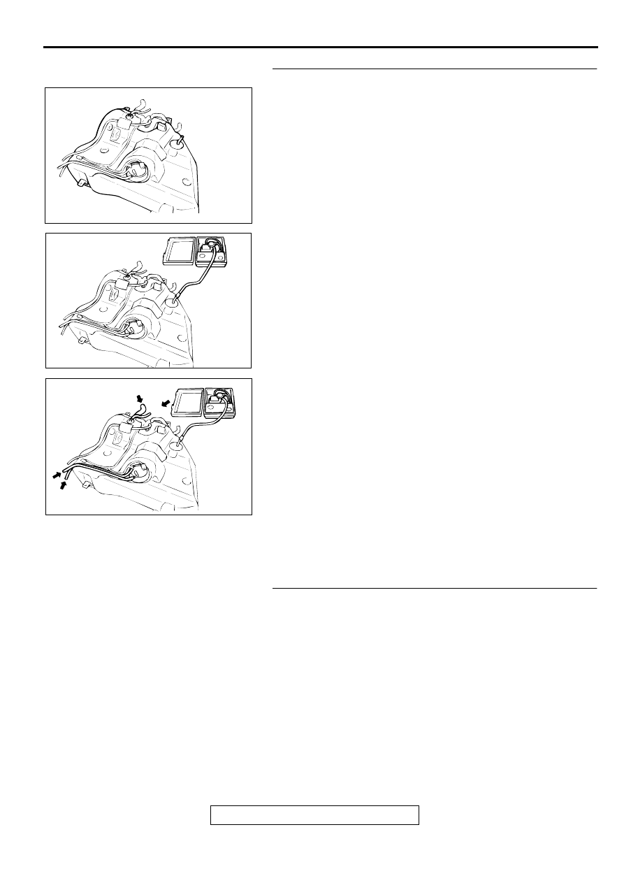
STEP 18. Check for leaks in the fuel tank.
(1) Visually check for cracks and leaks, etc.

NOTE: Carefully check the fuel pump assembly and the 
inner pressure sensor installation section in the fuel tank.

(2) Connect an evaporative emission system pressure pump to 

the leveling valve nipple.

(3) Plug the filler hose, feed pipe, return pipe and rollover valve 

nipple connected to the fuel tank.

NOTE: If these items are not securely plugged here, the 
fuel could leak in the next step.

(4) Apply pressure with the evaporative emission system 

pressure pump.

(5) In the pressurized state, check for the leak by applying soap 

water, etc. to each section.

Q: Can the leaks be pinpointed?

There is leaks at the fuel pump assembly or the inner 
pressure sensor installation section : 
Reassemble the 

parts, check again that there are no leaks, reinstall 
the fuel tank. Then go to Step 34.

There is leaks at another section : Go to Step 19.

STEP 19. Visually check for cracks in the fuel tank filler 
neck.
(1) Visually check for cracks in the fuel tank filler neck.

Q: Can the leaks be found out?

YES : Replace the fuel tank filler neck assembly and 

reinstall the fuel tank. Then go to Step 34.

NO :  Reinstall the fuel tank.Then go to Step 34.

AC000196

AC000197

AC000198

MULTIPORT FUEL INJECTION(MFI) DIAGNOSIS

TSB Revision

MULTIPORT FUEL INJECTION (MFI) <2.4L>

13A-258

STEP 20. Check for leaks in the evaporator line from hose 
H to hose I.
(1) The leakage test with a hand vacuum pump on each hose 

from hose H to hose I.

Q: Can the leaks be pin pointed?

YES : Replace that hose, and go to Step 34.
NO :  Go to Step 34.

STEP 21. Check for clogging in the evaporator line from 
hose E to hose G.
(1) Unplug hose E.
(2) On the EVAP pressure pump, set the pressure/hold valve to 

OPEN, and set the vent valve to CLOSED. Turn the pump 
timer to ON. You can reset the timer as required. (These 
settings are listed under "Leak Test" in the pump 
instructions.)

(3) Air should pass through hose E.

Q: Does air pass through hose E?

YES : Go to Step 25.
NO :  Go to Step 22.

AC002033 AD

HOSE H

HOSE I

OPEN

OPEN

CLOSED

CLOSED

Pressure
   Hold

Vent

ACX01806

AC002029

HOSE E

AC

MULTIPORT FUEL INJECTION(MFI) DIAGNOSIS

TSB Revision

MULTIPORT FUEL INJECTION (MFI) <2.4L>

13A-259

STEP 22. Check for clogging in the evaporator line from 
hose G to hose N.
(1) Disconnect hose G from the evaporative emission canister 

side, and unplug the hose G.

(2) On the EVAP pressure pump, set the pressure/hold valve to 

OPEN, and set the vent valve to CLOSED. Turn the pump 
timer to ON. You can reset the timer as required. (These 
settings are listed under "Leak Test" in the pump 
instructions.)

(3) Air should pass through hose G.

Q: Does air pass through hose G?

YES : Go to Step 23.
NO :  Go to Step 29.

STEP 23. Check for clogging in the evaporator line from 
hose E and hose F.
(1) Remove the fuel tank. (Refer to GROUP 13C, Fuel 

Tank

P.13C-6

.)

(2) The clogging test with a hand vacuum pump on each hose 

from hose E and hose F.

Q: Are there any clogs?

YES : Replace that hose, and perform the OBD-II drive 

cycle

P.13A-5

.

NO :  Go to Step 24.

AC002036 AC

HOSE G

OPEN

OPEN

CLOSED

CLOSED

Pressure
   Hold

Vent

ACX01806

AC002037

HOSE E

HOSE F

AF

MULTIPORT FUEL INJECTION(MFI) DIAGNOSIS

TSB Revision

MULTIPORT FUEL INJECTION (MFI) <2.4L>

13A-260

STEP 24. Check for clogging in the evaporative emission 
canister.
(1) Connect a hand vacuum pump to the vent nipple of the 

evaporative emission canister.

(2) Plug the other two nipples or loop a hose between the other 

nipples.

(3) Apply a vacuum, when each nipple is unplugged, the 

vacuum should fluctuate.

Q: Does the vacuum pump gauge reading fluctuate?

YES : Reinstall the fuel tank. Then go to step 34.
NO :  Replace the evaporative emission canister, reinstall 

the fuel tank. Then perform the OBD-II drive 
cycle

P.13A-5

.

STEP 25. Check for clogging in the evaporator line hose D.
(1) Disconnect hose D at the intake manifold side, and then 

connect a hand vacuum pump to hose D at the floor pipe 
side.

(2) Apply vacuum.

NOTE: The vacuum should be 40 kPa (5.8 psi) or less.

(3) Use scan tool MB991502 to activate the evaporative 

emission purge solenoid valve. The vacuum should leak.

Q: Is the vacuum maintained inside the evaporator line?

YES : Go to Step 26.
NO :  Go to Step 28.

STEP 26. Check for clogging in the evaporator line hose B 
to hose C.
(1) The clogging test with a hand vacuum pump on each hose 

from hose B to hose C.

Q: Are there any clogs?

YES : Replace that hose, and perform the purge flow check. 

(Refer to GROUP 17, Purge Control System 
Check

P.17-85

.)

NO :  Go to step 27.

STEP 27. Check for clogging in the chamber.
(1) Connect a hand vacuum pump to the nipple.
(2) Plug the other nipple.
(3) Apply vacuum. When the nipple is unplugged, the vacuum 

should fluctuate.

Q: Does the vacuum pump gauge reading fluctuates?

YES : Go to Step 34.
NO :  Replace the chamber, and perform OBD-II drive 

cycle

P.13A-5

.

AC000191AB

VENT
NIPPLE

AC000227

HOSE D

AC

AC000223

HOSE B

AC

HOSE C


Content   ..  142  143  144  145   ..