Mitsubishi Galant. Manual - part 138


  Index      Mitsubishi     Mitsubishi Galant - service repair manual 2001 year


Search            


Content   ..  136  137  138  139   ..


Mitsubishi Galant. Manual - part 138


MULTIPORT FUEL INJECTION(MFI) DIAGNOSIS

TSB Revision

MULTIPORT FUEL INJECTION (MFI) <2.4L>

13A-233

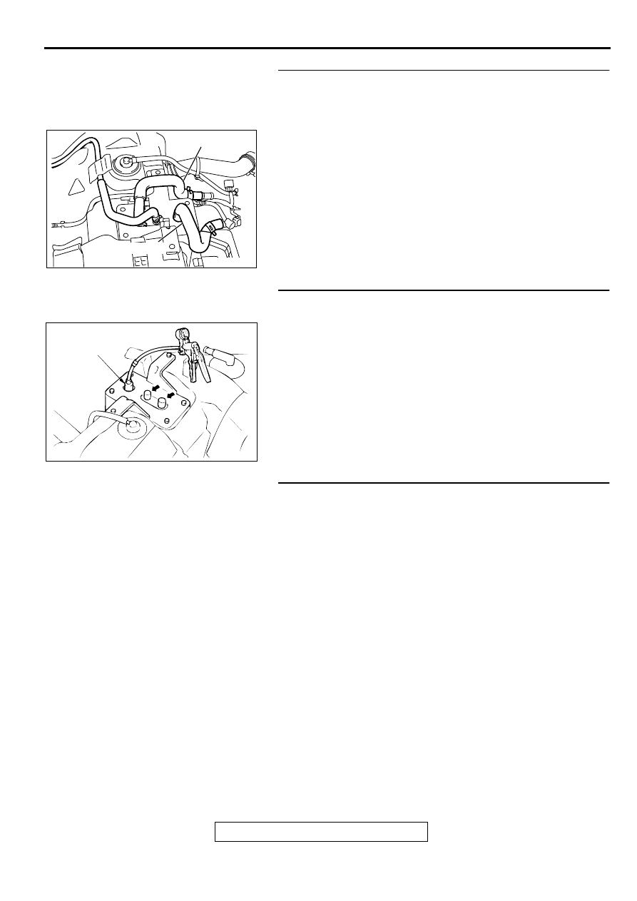
STEP 24. Check for clogging in the evaporator line from 
hose E and hose F.
(1) Remove the fuel tank. (Refer to GROUP 13C, Fuel 

Tank

P.13C-6

.)

(2) Carry out the clogging test with a hand vacuum pump on 

each hose from hose E and hose F.

Q: Are there any clogs?

YES : Replace that hose, reinstall the fuel tank. Then go to 

Step 26.

NO :  Go to Step 25.

STEP 25. Check for clogging in the evaporative emission 
canister.
(1) Connect a hand vacuum pump to the vent nipple of the 

evaporative emission canister.

(2) Plug the other two nipples or loop a hose between the other 

nipples.

(3) Apply vacuum. When each nipple is unplugged, the vacuum 

should fluctuate.

Q: Does the vacuum pump gauge reading fluctuate?

YES : Reinstall the fuel tank. Then go to Step 26.
NO :  Replace the evaporative emission canister, reinstall 

the fuel tank. Then go to Step 26.

STEP 26. Test the OBD-II drive cycle.
(1) Carry out a test drive with the drive cycle pattern. (Refer to 

P.13A-5

, Procedure 1 

 Evaporative Emission Control 

system Leak Monitor.)

(2) Read the diagnostic trouble code P0450 does not reset.

Q: Are the DTCs reset?

YES : This diagnosis is complete. (If no malfunctions are not 

found in all steps, an intermittent malfunction is 
suspected.) Refer to GROUP 00, How to Use 
Troubleshooting/Inspection Service Points 

 How to 

Cope with Intermittent Malfunction

P.00-8

.

NO :  Replace the PCM.

AC002037

HOSE E

HOSE F

AF

AC000191AB

VENT
NIPPLE

MULTIPORT FUEL INJECTION(MFI) DIAGNOSIS

TSB Revision

MULTIPORT FUEL INJECTION (MFI) <2.4L>

13A-234

DTC P0451: Evaporative Emission Control System Pressure Sensor Range/Performance

AC001943

A

B

C

EVAPORATIVE EMISSION 
PURGE SOLENOID

EVAPORATIVE 
EMISSION CANISTER

EVAPORATIVE 
EMISSION 
VENTILATION 
SOLENOID

FUEL TANK

CHECK VALVE A

CHECK 
VALVE B

INTAKE MANIFOLD

SYSTEM DIAGRAM

D

E

F

G

I

H

L

N

M

K

J

O

P

CHAMBER

AC

FUEL TANK DIFFRENTIAL 
PRESSURE SENSOR

MULTIPORT FUEL INJECTION(MFI) DIAGNOSIS

TSB Revision

MULTIPORT FUEL INJECTION (MFI) <2.4L>

13A-235

Fuel Tank Differential Pressure Sensor Circuit

MULTIPORT FUEL INJECTION(MFI) DIAGNOSIS

TSB Revision

MULTIPORT FUEL INJECTION (MFI) <2.4L>

13A-236

CIRCUIT OPERATION

A 5-volt voltage is supplied to the power terminal 
of the fuel tank differential pressure sensor 
(terminal 3) from the PCM (terminal 46.) The 
ground terminal (terminal 2) is grounded with the 
PCM (terminal 57.)

A voltage proportional to the pressure in the fuel 
tank is sent from the output terminal of the fuel 
tank differential pressure sensor (terminal 1) to 
the PCM (terminal 92.)

TECHNICAL DESCRIPTION

To judge if the fuel tank differential pressure 
sensor is defective, the PCM monitors the fuel 
tank differential pressure sensor output voltage.

There are three different sets (A, B, C) of test 
conditions and the judgment criteria. Based on 
these test conditions and judgment criteria, the 
PCM judges if the fuel tank differential pressure 
sensor output voltage is normal.

NOTE: In rare cases, this DTC may be also set 
under some fuel and driving conditions regardless of 
the fuel pressure sensor output voltage when the fuel 
system is clogged.

DTC SET CONDITIONS

Test Conditions A: Fuel tank differential pressure 

sensor output voltage is less than the upper 
limit of the predetermined value

Intake air temperature is higher than 5

°

C (41

°

F.)

Engine speed is 1,600 r/min or more.

Volumetric efficiency is between 25 and 80 
percent.

Vehicle speed is 30 km/h (18.7 mph) or more.

Evaporative emission purge solenoid is driven at 
a 100 percent duty when the intake air 
temperature is between 5 and 45

°

C (41 

 113

°

F.)

Judgement Criteria A

The sensor output voltage remains 4.0 V or more 
for 10 seconds or more.

AC005041AB

CONNECTOR:C-17

AC005043

CONNECTORS : C-40, C-41

C-41

C-40

PCM

AB

AC005042 AB

CONNECTOR:C-71

AC002041AC

CONNECTOR: D-11

FUEL TANK DIFFERENTIAL 
PRESSURE SENSOR

AC005044 AB

CONNECTOR:D-15


Content   ..  136  137  138  139   ..