Mitsubishi Galant. Manual - part 128


  Index      Mitsubishi     Mitsubishi Galant - service repair manual 2001 year


Search            


Content   ..  126  127  128  129   ..


Mitsubishi Galant. Manual - part 128


MULTIPORT FUEL INJECTION(MFI) DIAGNOSIS

TSB Revision

MULTIPORT FUEL INJECTION (MFI) <2.4L>

13A-193

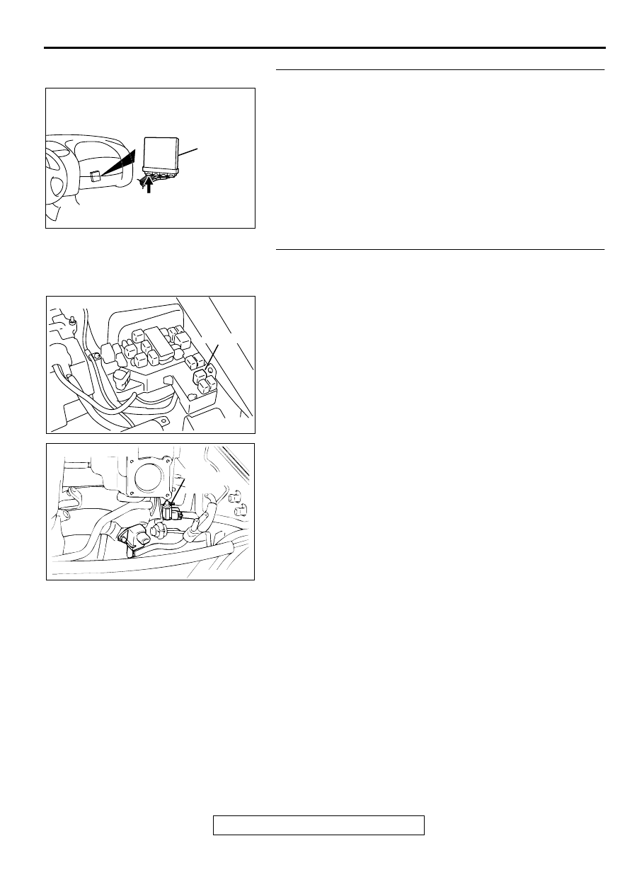
STEP 9. Check connector C-39 at PCM for damage.
Q: Is the connector in good condition?

YES : Go to Step 10.
NO :  Repair or replace it. Refer to GROUP 00E, Harness 

Connector Inspection(

P.00E-2

). Then go to Step 12.

STEP 10. Check for harness damage between MFI relay 
connector A-21X terminal 1 and EGR solenoid connector 
B-03 terminal 1.
NOTE: Check harness after checking intermediate connector 
B-11.If intermediate connectors is damaged, repair or replace 
them.Refer to GROUP 00E, Harness Connector 
Inspection(

P.00E-2

).Then go to Step 12.

Q: Is the harness wire in good condition?

YES : Go to Step 11.
NO :  Repair it. Then go to Step 12.

AK000280

CONNECTOR : C-39

PCM

AW

AK000555AB

CONNECTOR : A-21X

MFI RELAY

ACX02513

CONNECTOR : B-03

AG

EGR
SOLENOID
VALVE

MULTIPORT FUEL INJECTION(MFI) DIAGNOSIS

TSB Revision

MULTIPORT FUEL INJECTION (MFI) <2.4L>

13A-194

STEP 11. Check for harness damage between EGR 
solenoid connector B-03 terminal 2 and PCM connector C-
39 terminal 6.
NOTE: Check harness after checking intermediate connector 
B-11.If intermediate connectors is damaged, repair or replace 
them.Refer to GROUP 00E, Harness Connector 
Inspection(

P.00E-2

).Then go to Step 12.

Q: Is the harness wire in good condition?

YES : Replace the PCM. Then go to Step 12.
NO :  Repair it. Then go to Step 12.

STEP 12. Test the OBD-II drive cycle.
(1) Carry out a test drive with the drive cycle pattern. Refer to, 

Procedure 6 

 Other Monitor

P.13A-5

.

(2) Check the diagnostic trouble code (DTC). 

Q: Is the DTC P0403 is output?

YES : Retry the troubleshooting.
NO :  The inspection is complete.

DTC P0421: Warm Up Catalyst Efficiency Below Threshold 

TECHNICAL DESCRIPTION

The signal from the rear heated oxygen sensor 
differs from the front heated oxygen sensor.That 
is because the catalytic converter purifies 
exhaust gas. When the catalytic converter has 
deteriorated, the signal from the front heated 
oxygen sensor becomes similar to the rear 
heated oxygen sensor.

The PCM compares the output of the front and 
rear heated oxygen sensor signals.

DTC SET CONDITIONS

Check Conditions

Engine speed is lower than 3,000 r/min.

Volume air flow sensor output frequency is 
between 63 and 169 Hz.

Intake air temperature is higher than -10

° 

C (14

° 

F).

Barometric pressure is higher than 76 kPa (11 
psi).

The throttle valve is open.

Under the closed loop air / fuel ratio control.

Vehicle speed is 1.5 km/h (0.93 mph) or more.

Monitoring time: 70 seconds.

Judgment Criteria

The heated oxygen sensor (rear) signal and 
heated oxygen sensor (front) signal are similar.

ACX02513

CONNECTOR : B-03

AG

EGR
SOLENOID
VALVE

AK000280

CONNECTOR : C-39

PCM

AW

MULTIPORT FUEL INJECTION(MFI) DIAGNOSIS

TSB Revision

MULTIPORT FUEL INJECTION (MFI) <2.4L>

13A-195

TROUBLESHOOTING HINTS (The most likely 
causes for this code to be set are:)

Catalytic converter deteriorated.

Heated oxygen sensor failed.

PCM failed.

DIAGNOSIS

Required Special Tools
MB991502: Scan Tool (MUT-II)

STEP 1. Check the exhaust leaks.

Q: Are there any abnormalities?

YES : Go to Step 2.
NO :  Repair it. Then go to Step 7.

STEP 2. Using scan tool MB991502, check data list item 59: 
Heated Oxygen Sensor (rear).

CAUTION

To prevent damage to scan tool MB991502, always turn the 
ignition switch to the "LOCK"(OFF) position before 
connecting or disconnecting scan tool MB991502.
(1) Connect scan tool MB991502 to the data link connector.
(2) Start the engine and run at idle.
(3) Set scan tool MB991502 to the data reading mode for item 

59, Heated Oxygen Sensor (rear).

Warming up the engine. When the engine is revved, the 
output voltage should repeat 0 volt and 0.6 to 1.0 volt 
alternately.

(4) Turn the ignition switch to the "LOCK"(OFF) position.

Q: Is the sensor operating properly?

YES : Go to Step 3.
NO :  Refer to, DTC P0136 

 O

2

 Sensor Circuit Malfunction 

(sensor 2)(

P.13A-127

), DTC P0139 

 O

Sensor 

Circuit Slow Response (sensor 2)(

P.13A-135

).

STEP 3. Using scan tool MB991502, check data list item 11: 
Heated Oxygen Sensor (front).
(1) Start the engine and run at idle.
(2) Set scan tool MB991502 to the data reading mode for item 

11, Heated Oxygen Sensor (front).

Warming up the engine. When the engine is revved, the 
output voltage should be 0.6 to 1.0 volt.

(3) Turn the ignition switch to the "LOCK"(OFF) position.

Q: Is the sensor operating properly?

YES : Go to Step 4.
NO :  Refer to, DTC P0130 

 O

2

 Sensor Circuit Malfunction 

(sensor 1)(

P.13A-105

), DTC P0133 

 O

2

 Sensor 

Circuit Slow Response (sensor 1)(

P.13A-113

).

AC003081 AB

16 PIN

MB991502

AC003081 AB

16 PIN

MB991502

MULTIPORT FUEL INJECTION(MFI) DIAGNOSIS

TSB Revision

MULTIPORT FUEL INJECTION (MFI) <2.4L>

13A-196

STEP 4. Using scan tool MB991502, check data list item 11: 
Heated Oxygen Sensor (front).
(1) Start the engine and run at idle.
(2) Set scan tool MB991502 to the data reading mode for item 

11, Heated Oxygen Sensor (front).

(3) Keep the engine speed at 2,000 r/min.

 0.4 and 0.6 

 1.0 volt should alternate 15 times or 

more within 10 seconds.

(4) Turn the ignition switch to the "LOCK"(OFF) position.

Q: Is the sensor operating properly?

YES : Go to Step 5.
NO :  Replace the heated oxygen sensor (front). Then go to 

Step 7.

STEP 5. Test the OBD-II drive cycle.
(1) Carry out a test drive with the drive cycle pattern. Refer to, 

Procedure 3 

 Catalytic Converter Monitor(

P.13A-5

).

(2) Check the diagnostic trouble code (DTC).

Q: Is the DTC P0421 is output?

YES : Replace the right bank side catalytic converter. Then 

go to Step 6.

NO :  The inspection is complete.

STEP 6. Test the OBD-II drive cycle.
(1) Carry out a test drive with the drive cycle pattern. Refer to, 

Procedure 3 

 Catalytic Converter Monitor(

P.13A-5

).

(2) Check the diagnostic trouble code (DTC).

Q: Is the DTC P0421 is output?

YES : Replace the PCM. Then go to Step 7.
NO :  The inspection is complete.

STEP 7. Test the OBD-II drive cycle.
(1) Carry out a test drive with the drive cycle pattern. Refer to, 

Procedure 3 

 Catalytic Converter Monitor(

P.13A-5

).

(2) Check the diagnostic trouble code (DTC).

Q: Is the DTC P0421 is output?

YES : Retry the troubleshooting.
NO :  The inspection is complete.

AC003081 AB

16 PIN

MB991502


Content   ..  126  127  128  129   ..