Mitsubishi Galant. Manual - part 126


  Index      Mitsubishi     Mitsubishi Galant - service repair manual 2001 year


Search            


Content   ..  124  125  126  127   ..


Mitsubishi Galant. Manual - part 126


MULTIPORT FUEL INJECTION(MFI) DIAGNOSIS

TSB Revision

MULTIPORT FUEL INJECTION (MFI) <2.4L>

13A-185

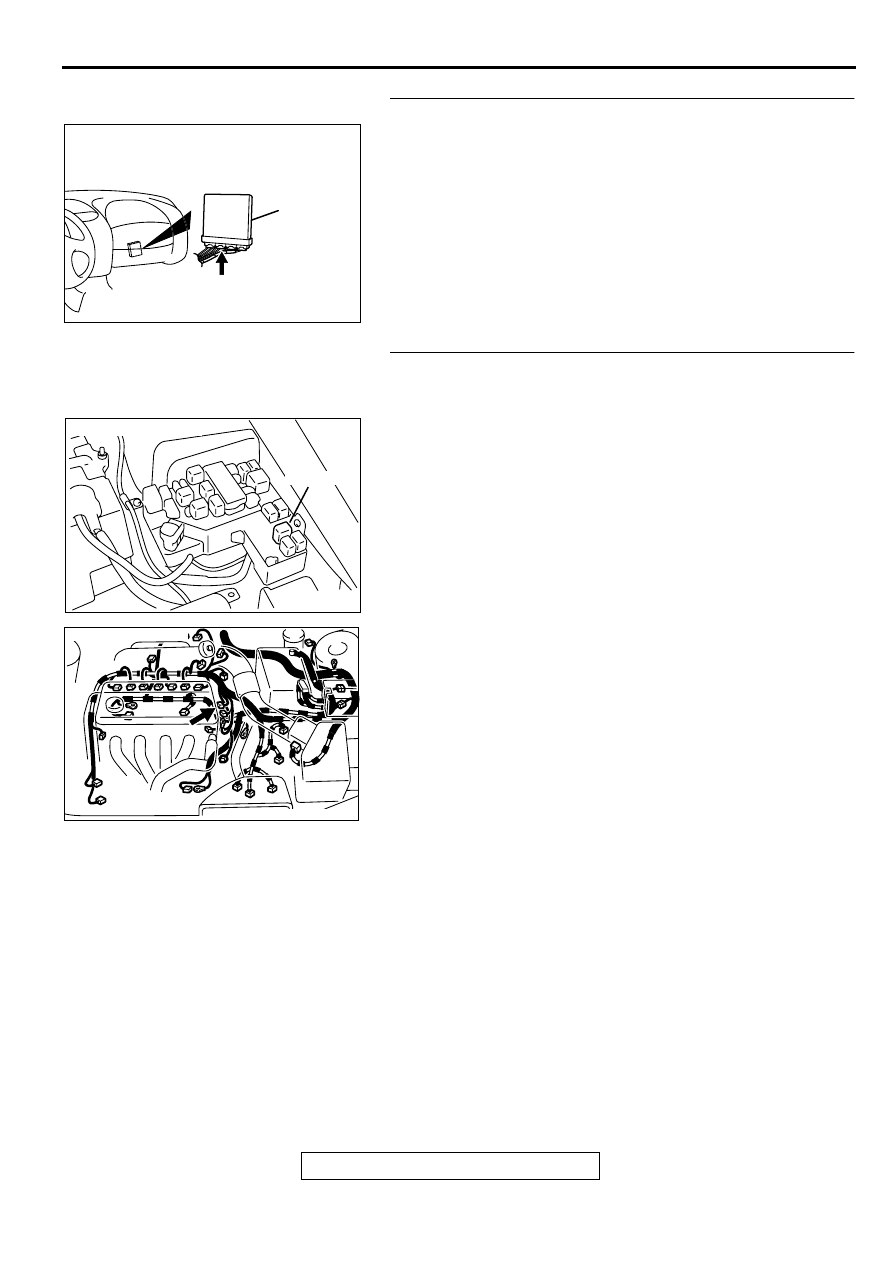
STEP 14. Check connector C-40 at PCM for damage.
Q: Is the connector in good condition?

YES : Go to Step 15.
NO :  Repair or replace it. Refer to GROUP 00E, Harness 

Connector Inspection (

P.00E-2

). Then go to Step 19.

STEP 15. Check for harness damage between MFI relay 
connector A-21X terminal 1 and camshaft position sensor 
connector B-12 terminal 3.
Q: Is the harness wire in good condition?

YES : Go to Step 16.
NO :  Repair it. Then go to Step 18.

AK000280

CONNECTOR : C-40

PCM

AV

AK000555AB

CONNECTOR : A-21X

MFI RELAY

AK000563AB

CONNECTOR:B-12

MULTIPORT FUEL INJECTION(MFI) DIAGNOSIS

TSB Revision

MULTIPORT FUEL INJECTION (MFI) <2.4L>

13A-186

STEP 16. Check for harness damage between camshaft 
position sensor connector B-12 terminal 2 and PCM 
connector C-40 terminal 56.
Q: Is the harness wire in good condition?

YES : Go to Step 17.
NO :  Repair it. Then go to Step 18.

STEP 17. Check the camshaft position sensor vane.

Q: Is the vane in a good condition?

YES : Replace the camshaft position sensor. Then go to 

Step 18. 

NO :  Repair it. Then go to Step 18.

STEP 18. Test the OBD-II drive cycle.
(1) Carry out a test drive with the drive cycle pattern. Refer to, 

Procedure 6 

 Other Monitor(

P.13A-5

).

(2) Check the diagnostic trouble code (DTC).

Q: Is the DTC P0340 is output?

YES : Retry the troubleshooting.
NO :  The inspection is complete.

DTC P0401: Exhaust Gas Recirculation Flow Insufficient Detected

TECHNICAL DESCRIPTION

When the EGR solenoid switches from "OFF" to 
"ON" while the engine is running, EGR gas flows.

The PCM checks how the EGR gas flow signal 
changes.

DTC SET CONDITIONS

Check Conditions

At least twenty seconds have passed since the 
last monitor was complete.

Engine coolant temperature is higher than 82

°

 C 

(180

°

 F).

Engine speed is at between 940 and 2,000 r/min.

Intake air temperature is higher than 5

°

 C (41

°

 F).

AK000563AB

CONNECTOR:B-12

AK000280

CONNECTOR : C-40

PCM

AV

MULTIPORT FUEL INJECTION(MFI) DIAGNOSIS

TSB Revision

MULTIPORT FUEL INJECTION (MFI) <2.4L>

13A-187

Barometric pressure is higher than 76 kPa (11 
psi).

Vehicle speed is 30 km/h (18.7 mph) or more.

At least ninety seconds have passed since 
manifold differential pressure sensor output 
voltage fluctuated 1.5 volts or more.

The throttle valve is closed.

Volumetric efficiency is lower than 20 percent.

Monitoring time: 2 seconds.

Judgement Criteria

The intake manifold pressure fluctuations are 
minimal. When the EGR solenoid is turned ON.

Three monitors during one drive cycle

TROUBLESHOOTING HINTS (The most likely 
causes for this code to be set are:)

EGR valve does not open.

EGR control vacuum is too low.

EGR solenoid failed.

Open or shorted EGR solenoid circuit, or loose 
connector.

Manifold differential pressure sensor failed.

PCM failed.

DIAGNOSIS

Required Special Tools
MB991502: Scan Tool (MUT-II)

STEP 1. Check the EGR system
Refer to GROUP 17, Emission Control System 

 Exhaust Gas 

Recirculation (EGR) System - EGR System Check (

P.17-91

).

Q: Are there any abnormalities?

YES : Go to Step 2.
NO :  Repair it. Then go to Step 3.

STEP 2. Using scan tool MB991502, check data list item 95: 
Manifold Differential Pressure Sensor.

CAUTION

To prevent damage to scan tool MB991502, always turn the 
ignition switch to the "LOCK"(OFF) position before 
connecting or disconnecting scan tool MB991502.
(1) Connect scan tool MB991502 to the data link connector.
(2) Start the engine and run at idle.
(3) Set scan tool MB991502 to the data reading mode for   item 

95, Manifold Differential Pressure Sensor.

(4) Warm up the engine to normal operating temperature: 80

°


C to 96

°

 C(176

° 

F to 205

° 

F).

Should be between 62 

 76 kPa at engine idling.

(5) Turn the ignition switch to the "LOCK"(OFF) position.

Q: Is the sensor operating properly?

YES : Clean the EGR valve and EGR passage. Then go to 

Step 3. 

NO :  Refer to, DTC P1400 

 Manifold Differential Pressure 

Sensor Circuit Malfunction(

P.13A-299

).

STEP 3. Test the OBD-II drive cycle.
(1) Carry out a test drive with the drive cycle pattern. Refer to, 

Procedure 5 

 Exhaust Gas Recirculation (EGR) System 

Monitor(

P.13A-5

).

(2) Check the diagnostic trouble code (DTC).

Q: Is the DTC P0401 is output?

YES : Retry the troubleshooting.
NO :  The inspection is complete.

AC003081 AB

16 PIN

MB991502

MULTIPORT FUEL INJECTION(MFI) DIAGNOSIS

TSB Revision

MULTIPORT FUEL INJECTION (MFI) <2.4L>

13A-188

DTC P0403: Exhaust Gas Recirculation Solenoid Malfunction

AK000471

3 4

1 2

1 2

5 6

3 4
7 8

2

1

RED-

WHITE

RED-

WHITE

RED-

WHITE

RED

RED

BLUE-

RED

BLUE-

BLA

CK

BATTERY

MFI
RELAY

A-21X

     B-11
MU802749

B-03

EGR SOLENOID

1

1

2

2

3

4

5

6

6

POWERTRAIN CONTROL
MODULE(PCM)

2

3 4

5 6

7 8

9

11 12 13 14 15 16 17 18 19 20

30

21 22 23

24 25

26 27 28 29

3132 33

34 35

1

10

      C-39
(MU803784)


Content   ..  124  125  126  127   ..