Mitsubishi Galant. Manual - part 86
MULTIPORT FUEL INJECTION(MFI) DIAGNOSIS
TSB Revision
MULTIPORT FUEL INJECTION (MFI) <2.4L>
13A-25
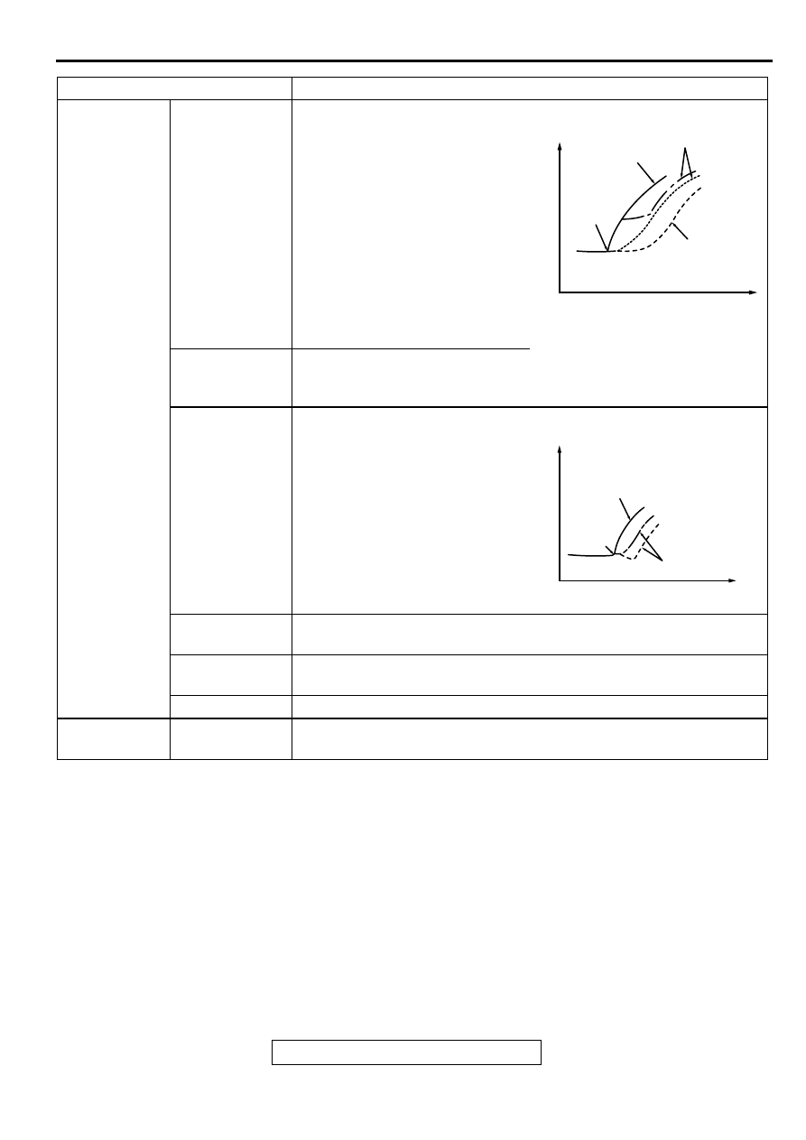
Driving
Hesitation Sag
" Hesitation " is the delay in
response of the vehicle speed
(engine speed). This occurs when
the accelerator is depressed in
order to accelerate from the speed
at which the vehicle is now
traveling, or a temporary drop in
vehicle speed (engine speed)
during such acceleration.
Serious hesitation is called " sag. "
Poor
acceleration
Poor acceleration is inability to obtain an acceleration corresponding to
the degree of throttle opening, even though acceleration is smooth or
the inability to reach maximum speed.
Stumble
Engine speed increase is delayed
when the accelerator pedal is
initially depressed for acceleration.
Shock
The feeling of a comparatively large impact or vibration when the
engine is accelerated or decelerated.
Surge
This is slight acceleration and deceleration feel usually felt during
steady, light throttle cruise. Most notable under light loads.
Knocking
A sharp sound during driving like a hammer striking the cylinder walls.
Stopping
Run on
("dieseling ")
The condition in which the engine continues to run after the ignition
switch is turned to off. Also called " dieseling. "
ITEMS
SYMPTOM
AKX01361
VEHICLE
SPEED
TIME
NORMAL
HESITATION
SAG
INITIAL
ACCELE-
RATOR
PEDAL
DEPRE-
SSION
AKX01361AB
AKX01362
VEHICLE
SPEED
TIME
NORMAL
STUMBLE
INITIAL
ACCEL-
ERATOR
PEDAL
DEP-
RESSION
IDLING