Mitsubishi Galant. Manual - part 57


  Index      Mitsubishi     Mitsubishi Galant - service repair manual 2001 year


Search            


Content   ..  55  56  57  58   ..


Mitsubishi Galant. Manual - part 57


ENGINE ASSEMBLY

TSB Revision

ENGINE MECHANICAL <3.0L>

11C-13

Required Special Tools:

MB991453: Engine Hanger Assembly

MZ203827: Engine Lifter

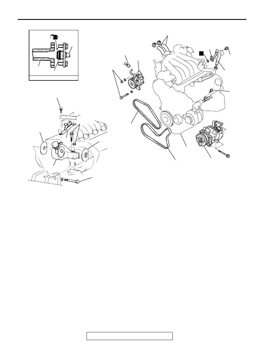
REMOVAL SERVICE POINTS

<<A>> A/C COMPRESSOR REMOVAL
Remove the A/C compressor from the compressor bracket with 
the hose attached.

NOTE: Place the removed A/C compressor where it will not be 
a hindrance when removing and installing the engine assembly, 
and secure it with a cord or wire.

AC005055

25

N

26

4.9 N·m
43 ft-lb

27

28

29

30

31

32

33

42 N·m
31 ft-lb

ENGINE OIL

FUEL RAIL

O-RING

25

34

36

36

35

37

35 N·m
26 ft-lb

86 N·m
63 ft-lb

81 N·m*
60 ft-lb*

AB

>>D<< 25. HIGH-PRESSURE FUEL HOSE 

CONNECTION

26. FUEL RETURN HOSE 

CONNECTION

27. HEATER HOSE CONNECTION
28. SUCTION HOSE CONNECTION
29. DRIVE BELT (GENERATOR AND 

A/C COMPRESSOR)

30. DRIVE BELT (POWER STEERING 

OIL PUMP)

<<A>>

31. A/C COMPRESSOR

32. POWER STEERING PRESSURE 

SWITCH CONNECTOR

<<B>>

33. POWER STEERING OIL PUMP
34. ENGINE MOUNT STAY

TRANSAXLE ASSEMBLY
(REFER TO GROUP 23A, 
TRANSAXLE ASSEMBLY 

P.23A-

290

.)

<<C>> >>C<<

35. ENGINE MOUNT BRACKET

>>B<<

36. ENGINE MOUNT STOPPER

<<D>> >>A<<

37. ENGINE ASSEMBLY

ENGINE ASSEMBLY

TSB Revision

ENGINE MECHANICAL <3.0L>

11C-14

<<B>> POWER STEERING OIL PUMP REMOVAL
Remove the power steering oil pump from the engine with the 
hose attached.

NOTE: Place the removed power steering oil pump in a place 
where it will not be a hindrance when removing and installing 
the engine assembly, and secure it with a cord or wire.

<<C>> ENGINE MOUNT BRACKET REMOVAL
1. Support the engine with a garage jack.
2. Remove special tools MB991453 and MZ203827 which 

were attached when the transaxle assembly was removed.

3. Hold the engine assembly with a chain block or similar tool.

4. Place a garage jack against the engine oil pan with a piece 

of wood in between, jack up the engine so that the weight of 
the engine is no longer being applied to the engine mount 
bracket, and then remove the engine mount bracket.

<<D>> ENGINE ASSEMBLY REMOVAL
After checking that all cables, hoses and harness connectors, 
etc., are disconnected from the engine, lift the chain block 
slowly to remove the engine assembly upward from the engine 
compartment.

INSTALLATION SERVICE POINTS

>>A<< ENGINE ASSEMBLY INSTALLATION
Install the engine assembly, checking that the cables, hoses, 
and harness connectors are not clamped.

>>B<< ENGINE MOUNT STOPPER INSTALLATION
Clamp the engine mount stopper so that the arrow points in the 
direction as shown in the diagram.

>>C<< ENGINE MOUNT BRACKET INSTALLATION
1. Place a garage jack against the engine oil pan with a piece 

of wood in between, and install the engine mount bracket 
while adjusting the position of the engine.

2. Support the engine with the garage jack.

AC000127

MZ203827

MB991453

AB

AC001714AB

ENGINE SIDE

ENGINE MOUNT
STOPPER

ENGINE MOUNT 
BRACKET

ARROW

ENGINE ASSEMBLY

TSB Revision

ENGINE MECHANICAL <3.0L>

11C-15

3. Remove the chain block and support the engine assembly 

with special tools MB991453 and MZ203827.

>>D<< HIGH-PRESSURE FUEL HOSE INSTALLATION

CAUTION

Do not allow engine oil to enter the fuel rail.
1. Apply a small amount of new engine oil to the O

ring.

2. Turning the high-pressure fuel hose to the right and left, 

install it to the fuel rail, while being careful not to damage the 
O-ring. After installing, check that the hose turns smoothly.

3. If the hose does not turn smoothly, the O-ring may be 

clamped. Disconnect the high-pressure fuel hose and check 
the O-ring for damage. 

4. Re-insert the fuel rail and check that the hose turns 

smoothly.

AC000127

MZ203827

MB991453

AB

AC001715

HIGH-
PRESSURE
FUEL HOSE

O-RING

FUEL RAIL

AB

CAMSHAFT AND CAMSHAFT OIL SEAL

TSB Revision

ENGINE MECHANICAL <3.0L>

11C-16

C A M SH A FT A N D  C A M SH A FT O IL SEA L

REMOVAL AND INSTALLATION

M1112001900121

<LEFT BANK>

Required Special Tools:

MB990767: End Yoke Holder

MB991559: Camshaft Oil Seal Adapter

MD998443: Auto-lash Adjuster Holder

MD998713: Camshaft Oil Seal Installer

MD998715: Crankshaft Pulley Holder Pin

Pre-removal and Post-installation Operation

Timing Belt Removal and Installation (Refer to 

P.11C-29

.)

Thermostat Housing Assembly Removal and Installation 
(Refer to GROUP 14, Water Hose and Water Pip

P.14-

23

.)

AC004834

APPLY ENGINE OIL TO
ALL THE MOVING PARTS
WHEN INSTALLING

(ENGINE OIL)

3.4 N·m
30 in-lb

13 N·m
115 in-lb

88 N·m
65 ft-lb

28 – 34 N·m
21 – 25 ft-lb

1

2

3

5

6

7

8

10

11

AB

4

N

9

N

CAMSHAFT REMOVAL STEPS

1.

BLOW-BY HOSE CONNECTION

2.

PCV HOSE CONNECTION

3.

SPARK PLUG CABLE

4.

BATTERY CABLE CONNECTION

5.

ROCKER COVER

<<A>>

>>D<<

6.

ROCKER ARM AND SHAFT 
ASSEMBLY

<<B>>

>>B<<

7.

CAMSHAFT SPROCKET

9.

BATTERY CABLE AND 
HARNESS BRACKET 

10. THRUST CASE
11. CAMSHAFT

CAMSHAFT OIL SEAL 
REMOVAL STEPS

<<B>>

>>B<<

7.

CAMSHAFT SPROCKET

>>A<<

8.

CAMSHAFT OIL SEAL

CAMSHAFT REMOVAL STEPS 


Content   ..  55  56  57  58   ..