Mitsubishi Galant 9G. Manual - part 979


  Index      Mitsubishi     Mitsubishi Galant 9G - service repair manual


Search            


Content   ..  977  978  979  980   ..


Mitsubishi Galant 9G. Manual - part 979


MULTIPORT FUEL INJECTION (MFI) DIAGNOSIS

TSB Revision

MULTIPORT FUEL INJECTION (MFI) <3.8L ENGINE>

13B-216

• At least 20 seconds have passed since fuel shut 

off control was canceled.

• Monitoring time: 8 seconds.

Judgement Criteria

• Making the air/fuel ratio 15 percent richer for 8 

seconds does not result in raising the heated oxy-
gen sensor (front) output voltage beyond 0.2 volt.

.

OBD-II DRIVE CYCLE PATTERN

Refer to Diagnostic Function 

− OBD-II Drive Cycle − 

Procedure 6 

− Other Monitor 

P.13B-6

.

.

TROUBLESHOOTING HINTS (The most 
likely causes for this code to be set are:)

• Right bank heated oxygen sensor (front) failed.

• Short circuit in right bank heated oxygen sensor 

(front) output line.

• Connector damage.

• PCM failed.

DIAGNOSIS

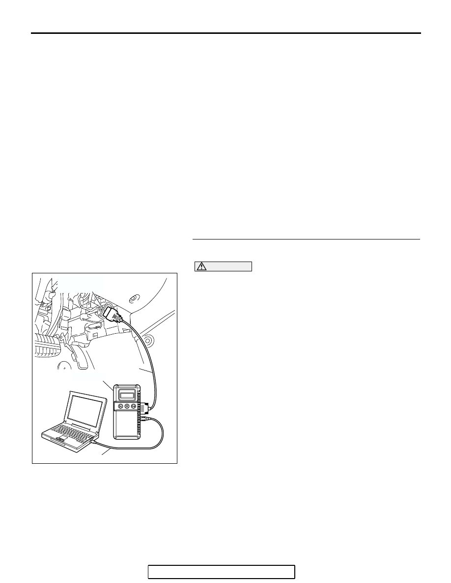
Required Special Tools:

• MB991958: Scan tool (MUT-III Sub Assembly)

• MB991824: V.C.I.

• MB991827: USB Cable

• MB991910: Main Harness A

• MD998464: Test Harness

STEP 1. Using scan tool MB991958, check data list item 39: 
Heated Oxygen Sensor Bank 1, Sensor 1 (right front).

CAUTION

To prevent damage to scan tool MB991958, always turn the 
ignition switch to the "LOCK" (OFF) position before con-
necting or disconnecting scan tool MB991958.
(1) Connect scan tool MB991958 to the data link connector.
(2) Start the engine and run at idle.

(3) Set scan tool MB991958 to the data reading mode for item 

39, Heated Oxygen Sensor Bank 1, Sensor 1 (right front).

• Warm up the engine. When the engine is revved, the 

output voltage should measure 0.6 to 1.0 volt.

• Warm up the engine. When the engine is idling, the out-

put voltage should repeat 0.4 volt and 0.6 to 1.0 volt 
alternately.

(4) Turn the ignition switch to the "LOCK" (OFF) position.
Q: Is the sensor operating properly?

YES : It can be assumed that this malfunction is intermittent. 

Refer to GROUP 00, How to Use 
Troubleshooting/Inspection Service Points 

− How to 

Cope with Intermittent Malfunctions 

P.00-14

.

NO :  Go to Step 2.

AC305412

AB

MB991910

DATA LINK

CONNECTOR

MB991824

MB991827

MULTIPORT FUEL INJECTION (MFI) DIAGNOSIS

TSB Revision

MULTIPORT FUEL INJECTION (MFI) <3.8L ENGINE>

13B-217

STEP 2. Check the right bank heated oxygen sensor 
(front).

(1) Disconnect the right bank heated oxygen sensor (front) 

connector B-09 and connect test harness special tool, 
MD998464, to the connector on the right bank heated 
oxygen sensor (front) side.

(2) Warm up the engine until engine coolant temperature 

reaches 80

°C (176°F) or higher.

(3) Perform a racing for 5 minutes or more with the engine 

speed of 4,500 r/min.

(4) Connect a digital voltage meter between terminal No. 2 

(black clip) and terminal No. 4 (white clip).

(5) While repeatedly revving the engine, measure the right 

bank heated oxygen sensor (front) output voltage.

Standard value: 0.6 

 1.0 volt

CAUTION

• Be very careful when connecting the jumper wires; 

incorrect connection can damage the heated oxygen 
sensor.

• Be careful the heater is broken when voltage of beyond 

8 volts is applied to the heated oxygen sensor heater.
NOTE: If the sufficiently high temperature [of approximate 
400

°

C (752

°

F) or more] is not reached although the heated 

oxygen sensor is normal, the output voltage would be possi-
bly low although the rich air/fuel ratio. Therefore, if the out-
put voltage is low, use a jumper wire to connect the terminal 
No.1 (red clip) and the terminal No. 3 (blue clip) of the 
heated oxygen sensor with the positive terminal and the 
negative terminal of 8 volts power supply respectively, then 
check again.

Q: Is the voltage between 0.6 and 1.0 volt?

YES : Go to Step 3.
NO :  Replace the right bank heated oxygen sensor (front). 

Then go to Step 5.

1

2

3

4

AK303048

B-09 (B)

CONNECTOR: B-09

THROTTLE BODY

RIGHT BANK
HEATED OXYGEN
SENSOR (FRONT)

AB

HARNESS
CONNECTOR:
COMPONENT SIDE

AKX01624

HEATED
OXYGEN
SENSOR
COMPONENT
SIDE
CONNECTOR

MD998464

WHITE

BLACK

AQ

MULTIPORT FUEL INJECTION (MFI) DIAGNOSIS

TSB Revision

MULTIPORT FUEL INJECTION (MFI) <3.8L ENGINE>

13B-218

STEP 3. Check harness connector B-09 at right bank 
heated oxygen sensor (front) and connector B-22 at PCM 
for damage.

Q: Is the harness connector in good condition?

YES : Go to Step 4.
NO :  Repair or replace it. Refer to GROUP 00E, Harness 

Connector Inspection 

P.00E-2

. Then go to Step 5.

1

2

3

4

AK303048

B-09 (B)

CONNECTOR: B-09

THROTTLE BODY

RIGHT BANK
HEATED OXYGEN
SENSOR (FRONT)

AB

HARNESS
CONNECTOR:
COMPONENT SIDE

AK303016

104

96

94

95

93 92 91

99 98 97

103 102 101 100

108 107 106 105

113 112 111 110 109

CONNECTOR: B-22

B-22 (B)

PCM

AB

HARNESS CONNECTOR: 
COMPONENT SIDE

AIR CLEANER

MULTIPORT FUEL INJECTION (MFI) DIAGNOSIS

TSB Revision

MULTIPORT FUEL INJECTION (MFI) <3.8L ENGINE>

13B-219

STEP 4. Check for short circuit to ground between right 
bank heated oxygen sensor (front) connector B-09 
(terminal No. 4) and PCM connector B-22 (terminal No. 92).

Q: Is the harness wire in good condition?

YES : Replace the PCM. Then go to Step 5.
NO :  Repair it. Then go to Step 5.

1

2

3

4

AK303048

B-09 (B)

CONNECTOR: B-09

THROTTLE BODY

RIGHT BANK
HEATED OXYGEN
SENSOR (FRONT)

AB

HARNESS
CONNECTOR:
COMPONENT SIDE

AK303016

104

96

94

95

93 92 91

99 98 97

103 102 101 100

108 107 106 105

113 112 111 110 109

CONNECTOR: B-22

B-22 (B)

PCM

AB

HARNESS CONNECTOR: 
COMPONENT SIDE

AIR CLEANER


Content   ..  977  978  979  980   ..