Mitsubishi Galant 9G. Manual - part 917
MULTIPORT FUEL INJECTION (MFI) DIAGNOSIS
TSB Revision
MULTIPORT FUEL INJECTION (MFI) <2.4L ENGINE>
13A-1110
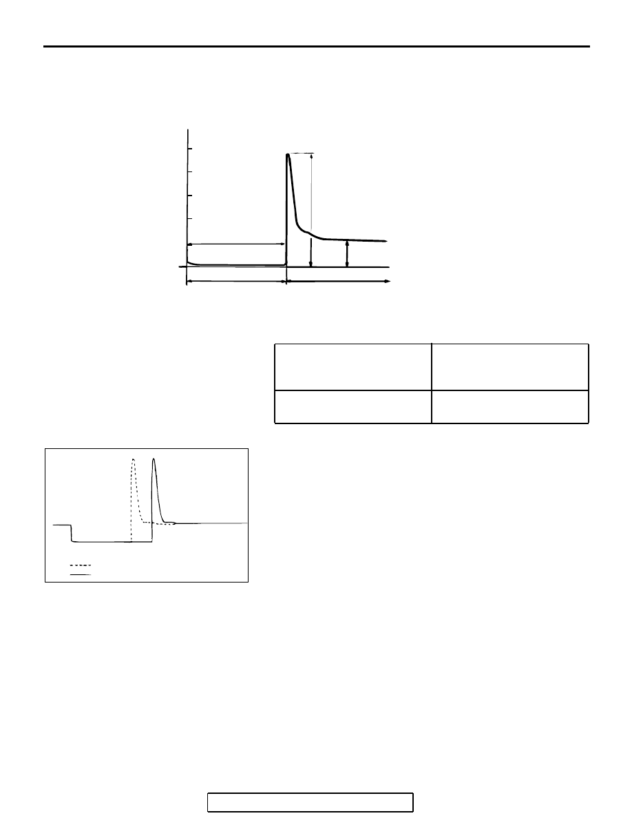
Wave Pattern Observation Points
Point A: Height of injector coil induced voltage.
Point B: Injector drive time
1. The injector drive time should be synchronized with the
scan tool tester display.
2. When the engine is suddenly revved, the drive time will be
greatly extended at first, but the drive time will soon return
to original length.
EGR VALVE (STEPPER MOTOR)
Required Special Tools:
• MB991658: Test Harness
• MB991923: Power Plant ECU Check Harness
.
CONTRAST WITH
STANDARD WAVE
PATTERN
PROBABLE CAUSE
Injector coil induced voltage is
low or doesn't appear at all
Short in the injector solenoid
AKX01604
(V)
50
0
DRIVE SIGNAL:"ON"
POINT B:
INJECTOR DRIVE
TIME
POINT A
DRIVE SIGNAL:"OFF"
POWER VOLTAGE
INJECTION COIL INDUCED
VOLTAGE (APPROXIMATELY 50-60 V)
AB
Standard wave pattern
AKX01605
WHEN IDLING
WHEN RACING
AB