Mitsubishi Galant 9G. Manual - part 916
MULTIPORT FUEL INJECTION (MFI) DIAGNOSIS
TSB Revision
MULTIPORT FUEL INJECTION (MFI) <2.4L ENGINE>
13A-1106
INSPECTION PROCEDURE USING AN
OSCILLOSCOPE
M1131154501074
CAMSHAFT POSITION SENSOR AND
CRANKSHAFT POSITION SENSOR
Required Special Tools:
• MB991709: Test Harness
• MB991658: Test Harness
• MB991923: Power Plant ECU Check Harness
.
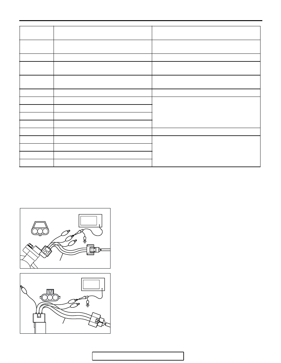
Measurement Method
1. Disconnect the camshaft position sensor connector, and
connect the test harness special tool (MB991709) between
the separated connector (All terminals should be
connected).
2. Connect the oscilloscope probe to camshaft position sensor
connector terminal No. 2.
3. Disconnect the crankshaft position sensor intermediate
connector, and connect the test harness special tool
(MB991658) between the separated connector.
4. Connect the oscilloscope probe to crankshaft position
sensor intermediate connector terminal No. 2.
.
51
− 126
Cylinder 1, 4 heated oxygen sensor heater
(front)
4.5
− 8.0 Ω [at 20°C (68°F)]
51
− 128
Engine oil control valve
6.9
− 7.9 Ω [at 20°C (68°F)]
51
− 137
Cylinder 2, 3 heated oxygen sensor heater
(rear)
11
− 18 Ω [at 20°C (68°F)]
51
− 138
Cylinder 1, 4 heated oxygen sensor heater
(rear)
11
− 18 Ω [at 20°C (68°F)]
141
− 147
Throttle actuator control motor
0.3
− 80 Ω [at 20°C (68°F)]
51
− 142
Stepper motor coil (A1)
20
− 24 Ω [at 20°C (68°F)]
51
− 136
Stepper motor coil (A2)
51
− 130
Stepper motor coil (B1)
51
− 124
Stepper motor coil (B2)
51
− 149
Evaporative emission purge solenoid
30
− 34 Ω [at 20°C (68°F)]
51
− 153
No. 1 injector
10.5
− 13.5 Ω [at 20°C (68°F)]
51
− 146
No. 2 injector
51
− 140
No. 3 injector
51
− 139
No. 4 injector
TERMINAL
NO.
INSPECTION ITEM
NORMAL CONDITION (INSPECTION
CONDITION)
AK102976AB
1 2 3
CAMSHAFT POSITION
SENSOR CONNECTOR
OSCILLOSCOPE
MB991709
AK302199
1 2 3
AB
MB991658
OSCILLOSCOPE
CRANKSHAFT POSITION
SENSOR INTERMEDIATE
CONNECTOR