Mitsubishi Galant 9G. Manual - part 869


  Index      Mitsubishi     Mitsubishi Galant 9G - service repair manual


Search            


Content   ..  867  868  869  870   ..


Mitsubishi Galant 9G. Manual - part 869


MULTIPORT FUEL INJECTION (MFI) DIAGNOSIS

TSB Revision

MULTIPORT FUEL INJECTION (MFI) <2.4L ENGINE>

13A-918

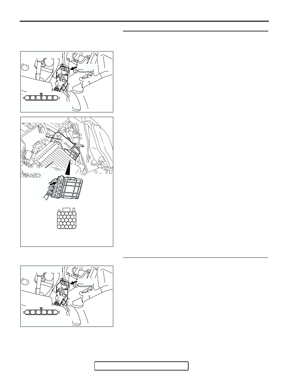
STEP 9. Check for harness damage between accelerator 
pedal position sensor connector C-24 (terminal No. 6) and 
PCM connector B-20 (terminal No. 27)
Q: Is the harness wire in good condition?

YES : Go to Step 10.
NO :  Repair it. Then go to Step 11.

STEP 10. Replace the accelerator pedal position sensor.
(1) Replace the accelerator pedal position sensor.
(2) Turn the ignition switch to the "ON" position.
(3) After the DTC has been deleted, read the DTC again.
(4) Turn the ignition switch to the "LOCK" (OFF) position.
Q: Is DTC P2127 set?

YES : Replace the PCM. Then go to Step 11.
NO :  The inspection is complete.

AK303906

1

6 5 4 3 2

AB

C-24 (B)

CONNECTOR: C-24

HARNESS CONNECTOR:
COMPONENT SIDE

AK303092

25

21

24 23 22

29 28 27 26

34 33 32 31 30

38 37 36 35

43 42 41 40 39

CONNECTOR: B-20

B-20

PCM

AB

HARNESS CONNECTOR: 
COMPONENT SIDE

AIR CLEANER

AK303906

1

6 5 4 3 2

AB

C-24 (B)

CONNECTOR: C-24

HARNESS CONNECTOR:
COMPONENT SIDE

MULTIPORT FUEL INJECTION (MFI) DIAGNOSIS

TSB Revision

MULTIPORT FUEL INJECTION (MFI) <2.4L ENGINE>

13A-919

STEP 11. Using scan tool MB991958, read the diagnostic 
trouble code (DTC).

CAUTION

To prevent damage to scan tool MB991958, always turn the 
ignition switch to the "LOCK"(OFF) position before con-
necting or disconnecting scan tool MB991958.
(1) Connect scan tool MB991958 to the data link connector.
(2) Turn the ignition switch to the "ON" position.
(3) After the DTC has been deleted, read the DTC again.
(4) Turn the ignition switch to the "LOCK"(OFF) position.
Q: Is DTC P2127 set?

YES : Retry the troubleshooting.
NO :  The inspection is complete.

AK303804AB

MB991910

DATA LINK
CONNECTOR

MB991824

MB991827

MULTIPORT FUEL INJECTION (MFI) DIAGNOSIS

TSB Revision

MULTIPORT FUEL INJECTION (MFI) <2.4L ENGINE>

13A-920

DTC P2128: Accelerator Pedal Position Sensor (sub) Circuit High Input

CAUTION

If DTC P2128 has been set, TCL related DTC 
U1120 is also set. After P2128 has been diag-
nosed, don't forget to erase DTC U1120.

.

22

21

23 24 25

26 27 28 29

30 31 32 33 34

35 36 37 38

39 40 41 42 43

6

1 2 3 4 5

AK303908

YELLO

W

-RED

PINK-GREEN

BR

O

W

N

C-24

5 V

21

4

ACCELERATOR PEDAL 

POSITION SENSOR
(SUB)

POWERTRAIN CONTROL 
MODULE (PCM)

27

22

6

5

Accelerator Pedal Position Sensor (sub) Circuit

B-20

HALL IC

AC305244

AK303904AB

ACCELERATOR
PEDAL POSITION
SENSOR

CONNECTOR: C-24

C-24 (B)

AK303085

CONNECTOR: B-20

PCM

AB

AIR CLEANER

B-20

MULTIPORT FUEL INJECTION (MFI) DIAGNOSIS

TSB Revision

MULTIPORT FUEL INJECTION (MFI) <2.4L ENGINE>

13A-921

CIRCUIT OPERATION

• A 5-volt power supply is applied on the accelera-

tor pedal position sensor (sub) power terminal 
(terminal No. 4) from the PCM (terminal No. 21).
The ground terminal (terminal No. 5) is grounded 
with PCM (terminal No. 22).

.

TECHNICAL DESCRIPTION

• The accelerator pedal position sensor (sub) out-

puts voltage which corresponds to the accelera-
tor pedal depression.

• The PCM checks whether the voltage is within a 

specified range.

.

DESCRIPTIONS OF MONITOR METHODS

Accelerator pedal position sensor (sub) output volt-

age is out of specified range.

.

MONITOR EXECUTION

Continuous

.

MONITOR EXECUTION CONDITIONS 
(Other monitor and Sensor)

Other Monitor (There is no temporary DTC stored 

in memory for the item monitored below)

• Not applicable

Sensor (The sensor below is determined to be 

normal)

• Not applicable

.

DTC SET CONDITIONS
Logic Flow Chart

.

AK303907

START

END

NO

NO

YES

YES

YES

NO

MALFUNCTION

GOOD

CONTINUOUS

FAILURE FOR 0.3sec

OUTPUT VOLTAGE > =4.8V

MONITORING

CONDITIONS


Content   ..  867  868  869  870   ..