Mitsubishi Galant 9G. Manual - part 786
MULTIPORT FUEL INJECTION (MFI) DIAGNOSIS
TSB Revision
MULTIPORT FUEL INJECTION (MFI) <2.4L ENGINE>
13A-586
.
CIRCUIT OPERATION
• The EGR valve power is supplied from the MFI
relay (terminal No. 4).
• The PCM (terminals No. 124, No. 130, No. 136,
No. 142) drives the stepper motor by sequentially
turning "ON" the power transistors in the PCM
and providing ground to the idle air control motor
(terminal No. 1, No. 3, No. 4, No. 6).
.
TECHNICAL DESCRIPTION
• To judge if there is open circuit in the EGR valve
(stepper motor) drive circuit, PCM measure the
surge voltage of the EGR valve motor coil.
.
DESCRIPTIONS OF MONITOR METHODS
Off-surge does not occur after stepper motor is oper-
ated on to off.
.
MONITOR EXECUTION
Continuous
.
MONITOR EXECUTION CONDITIONS
(Other monitor and Sensor)
Other Monitor (There is no temporary DTC stored
in memory for the item monitored below)
• EGR stepper motor monitor
Sensor (The sensor below is determined to be
normal)
• Mass airflow sensor
• Engine coolant temperature sensor
• Intake air temperature sensor
• Barometric pressure sensor
• Throttle position sensor
• Accelerator pedal position sensor
• Manifold absolute pressure sensor
.
AK303865
AK303865AB
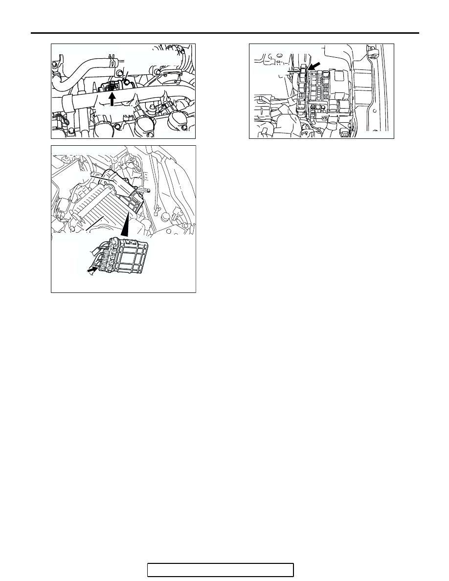
CONNECTOR: B-105
B-105 (GR)
EXHAUST GAS
RECIRCULATION
VALVE
AK303059
CONNECTOR: B-23
PCM
AB
AIR CLEANER
B-23
AK303803AB
CONNECTOR: B-17X
MFI RELAY
B-17X