Mitsubishi Galant 9G. Manual - part 769


  Index      Mitsubishi     Mitsubishi Galant 9G - service repair manual


Search            


Content   ..  767  768  769  770   ..


Mitsubishi Galant 9G. Manual - part 769


MULTIPORT FUEL INJECTION (MFI) DIAGNOSIS

TSB Revision

MULTIPORT FUEL INJECTION (MFI) <2.4L ENGINE>

13A-518

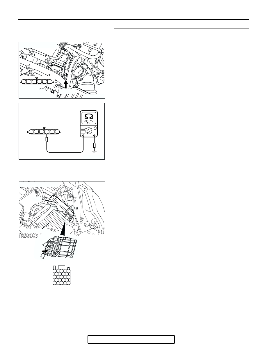
STEP 3. Check the continuity at throttle position sensor 
harness side connector B-06.
(1) Disconnect the connector B-06 and measure at the harness 

side.

(2) Measure the continuity between terminal No. 3 and ground.

• Should be less than 2 ohms.

Q: Does continuity exist?

YES : Go to Step 7.
NO :  Go to Step 4.

STEP 4. Check harness connector B-22 at PCM for 
damage.
Q: Is the harness connector in good condition?

YES : Go to Step 5.
NO :  Repair or replace it. Refer to GROUP 00E, Harness 

Connector Inspection 

P.00E-2

. Then go to Step 8.

AK303818

1

6 5 4 3 2

AB

CONNECTOR: B-06

B-06 (B)

HARNESS 
CONNECTOR:
COMPONENT SIDE

1

6 5 4 3 2

AK203051

B-06 HARNESS 
CONNECTOR: 
COMPONENT SIDE

AC

AK303016

104

96

94

95

93 92 91

99 98 97

103 102 101 100

108 107 106 105

113 112 111 110 109

CONNECTOR: B-22

B-22 (B)

PCM

AB

HARNESS CONNECTOR: 
COMPONENT SIDE

AIR CLEANER

MULTIPORT FUEL INJECTION (MFI) DIAGNOSIS

TSB Revision

MULTIPORT FUEL INJECTION (MFI) <2.4L ENGINE>

13A-519

STEP 5. Check for open circuit and harness damage 
between throttle position sensor connector B-06 (terminal 
No. 3) and PCM connector B-22 (terminal No. 95).
Q: Is the harness wire in good condition?

YES : Go to Step 6.
NO :  Repair it. Then go to Step 8.

AK303818

1

6 5 4 3 2

AB

CONNECTOR: B-06

B-06 (B)

HARNESS 
CONNECTOR:
COMPONENT SIDE

AK303016

104

96

94

95

93 92 91

99 98 97

103 102 101 100

108 107 106 105

113 112 111 110 109

CONNECTOR: B-22

B-22 (B)

PCM

AB

HARNESS CONNECTOR: 
COMPONENT SIDE

AIR CLEANER

MULTIPORT FUEL INJECTION (MFI) DIAGNOSIS

TSB Revision

MULTIPORT FUEL INJECTION (MFI) <2.4L ENGINE>

13A-520

STEP 6. Using scan tool MB991958, check data list item 14: 
Throttle Position Sensor (sub).

CAUTION

To prevent damage to scan tool MB991958, always turn the 
ignition switch to the "LOCK"(OFF) position before con-
necting or disconnecting scan tool MB991958
(1) Connect scan tool MB991958 to the data link connector.
(2) Turn the ignition switch to the "ON" position.
(3) Detach the intake air hose at the throttle body.
(4) Disconnect the connector of the throttle position sensor.
(5) Use test harness special tool (MB991658) to connect only 

terminals No. 3, No. 4, No. 5, and No. 6.

(6) Set scan tool MB991958 to the data reading mode for item 

14, Throttle Position Sensor (sub).

• Output voltage should be between 2.2 and 2.8 volts 

when the throttle valve is fully closed with your finger.

• Output voltage should be 4.0 volts or more when the 

throttle valve is fully open with your finger.

(7) Turn the ignition switch to the "LOCK"(OFF) position.
Q: Is the sensor operating properly?

YES : It can be assumed that this malfunction is intermittent. 

Refer to GROUP 00, How to Use 
Troubleshooting/Inspection Service Points 

− How to 

Cope with Intermittent Malfunctions 

P.00-14

.

NO :  Replace the PCM. Then go to Step 8. 

STEP 7. Replace the throttle body assembly.
(1) Replace the throttle body assembly.
(2) Turn the ignition switch to the "ON" position.
(3) After the DTC has been deleted, read the DTC again.
(4) Turn the ignition switch to the "LOCK" (OFF) position.
Q: Is DTC P0223 set?

YES : Replace the PCM. Then go to Step 8.
NO :  The inspection is complete.

AK303804AB

MB991910

DATA LINK
CONNECTOR

MB991824

MB991827

AK303818

1

6 5 4 3 2

AB

CONNECTOR: B-06

B-06 (B)

HARNESS 
CONNECTOR:
COMPONENT SIDE

MULTIPORT FUEL INJECTION (MFI) DIAGNOSIS

TSB Revision

MULTIPORT FUEL INJECTION (MFI) <2.4L ENGINE>

13A-521

STEP 8. Using scan tool MB991958, read the diagnostic 
trouble code (DTC).

CAUTION

To prevent damage to scan tool MB991958, always turn the 
ignition switch to the "LOCK"(OFF) position before con-
necting or disconnecting scan tool MB991958.
(1) Connect scan tool MB991958 to the data link connector.
(2) Turn the ignition switch to the "ON" position.
(3) After the DTC has been deleted, read the DTC again.
(4) Turn the ignition switch to the "LOCK"(OFF) position.
Q: Is DTC P0223 set?

YES : Retry the troubleshooting.
NO :  The inspection is complete.

DTC P0300: Random/Multiple Cylinder Misfire Detected

CAUTION

If DTC P0300 has been set, TCL related DTC 
U1120 is also set. After P0300 has been diag-
nosed, don't forget to erase DTC U1120.

.

TECHNICAL DESCRIPTION

• If a misfire occurs while the engine is running, the 

engine speed changes for an instant.

• The PCM checks for such changes in engine 

speed.

.

DESCRIPTIONS OF MONITOR METHODS

Monitor angular acceleration of crankshaft and 

detect malfunction when negative variation of the 
angular acceleration is large.

.

MONITOR EXECUTION

Continuous

.

MONITOR EXECUTION CONDITIONS 
(Other monitor and Sensor)

Other Monitor (There is no temporary DTC stored 

in memory for the item monitored below)

• Not applicable

Sensor (The sensor below is determined to be 

normal)

• Camshaft position sensor

• Mass airflow sensor

• Engine coolant temperature sensor

• Intake air temperature sensor

• Barometric pressure sensor

• Throttle position sensor

.

AK303804AB

MB991910

DATA LINK
CONNECTOR

MB991824

MB991827


Content   ..  767  768  769  770   ..