Mitsubishi Galant 9G. Manual - part 752
MULTIPORT FUEL INJECTION (MFI) DIAGNOSIS
TSB Revision
MULTIPORT FUEL INJECTION (MFI) <2.4L ENGINE>
13A-450
DTC SET CONDITIONS
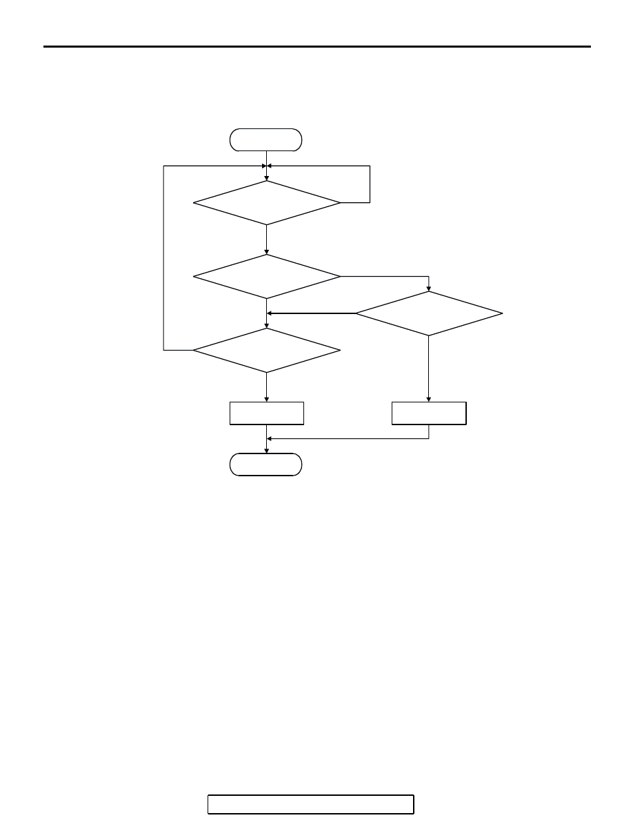
Logic Flow Chart
.
Check Conditions
• 2 seconds or more have passed since the engine
starting sequence was completed.
Judgement Criteria
• Sensor output voltage has continued to be 0.1
volt or lower for 2 seconds.
.
OBD-II DRIVE CYCLE PATTERN
Refer to Diagnostic Function
− OBD-II Drive Cycle −
Procedure 6
.
.
TROUBLESHOOTING HINTS (The most
likely causes for this code to be set are:)
• Fuel tank temperature sensor failed.
• Shorted fuel tank temperature sensor circuit or
connector damage.
• PCM failed.
DIAGNOSIS
Required Special Tools:
• MB991958: Scan Tool (MUT-III Sub Assembly)
• MB991824: V.C.I.
• MB991827: USB Cable
• MB991910: Main Harness A
START
MONITORING
CONDITIONS
END
NO
NO
NO
YES
YES
YES
MALFUNCTION
GOOD
OUTPUT VOLTAGE
< 0.1V
CONTINUOUS
FAILURE FOR
2secs
OUTPUT VOLTAGE
> 4.6V
NO
YES
AK302030