Mitsubishi Galant 9G. Manual - part 746


  Index      Mitsubishi     Mitsubishi Galant 9G - service repair manual


Search            


Content   ..  744  745  746  747   ..


Mitsubishi Galant 9G. Manual - part 746


MULTIPORT FUEL INJECTION (MFI) DIAGNOSIS

TSB Revision

MULTIPORT FUEL INJECTION (MFI) <2.4L ENGINE>

13A-426

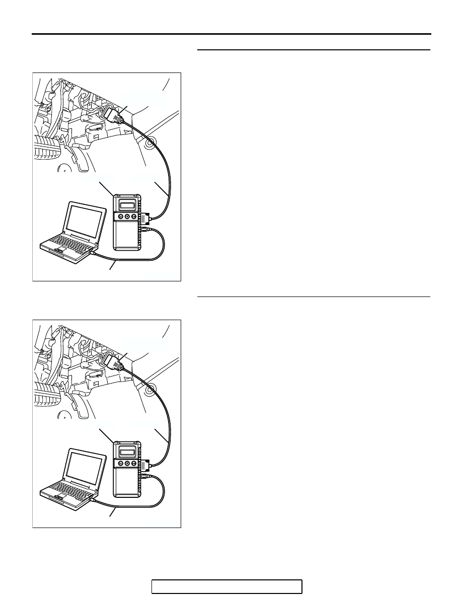
STEP 6. Using scan tool MB991958, check data list item 25: 
Barometric Pressure Sensor.
(1) Turn the ignition switch to the "ON" position.
(2) Set scan tool MB991958 to the data reading mode for item 

25, Barometric Pressure Sensor.

• When altitude is 0 m (0 foot), 101 kPa (29.8 in.Hg).

• When altitude is 600 m (1,969 feet), 95 kPa (28.1 in.Hg).

• When altitude is 1,200 m (3,937 feet), 88 kPa (26.0 

in.Hg).

• When altitude is 1,800 m (5,906 feet), 81 kPa (23.9 

in.Hg).

(3) Turn the ignition switch to the "LOCK" (OFF) position.
Q: Is the sensor operating properly?

YES : Go to Step 7.
NO :  Refer to, DTC P2228 

− Barometric Pressure Circuit 

Low Input 

P.13A-947

, DTC P2229 

− Barometric 

Pressure Circuit High Input 

P.13A-949

.

STEP 7. Using scan tool MB991958, check data list item 95: 
Manifold Absolute Pressure Sensor.
(1) Turn the ignition switch to the "ON" position.
(2) Set scan tool MB991958 to the data reading mode for item 

95, Manifold Absolute Pressure Sensor.

• When altitude is 0 m (0 foot), 101 kPa (29.8 in.Hg).

• When altitude is 600 m (1,969 feet), 95 kPa (28.1 in.Hg).

• When altitude is 1,200 m (3,937 feet), 88 kPa (26.0 

in.Hg).

• When altitude is 1,800 m (5,906 feet), 81 kPa (23.9 

in.Hg).

(3) Start the engine.

• When the engine is idling, 16 − 36 kPa (4.7 − 10.6 

in.Hg).

• When the engine is suddenly revved, manifold absolute 

pressure varies.

(4) Turn the ignition switch to the "LOCK" (OFF) position.
Q: Is the sensor operating properly?

YES : Go to Step 8.
NO :  Refer to DTC P0106 

− Manifold Absolute Pressure 

Circuit Range/Performance Problem 

P.13A-72

, DTC 

P0107 

− Manifold Absolute Pressure Circuit Low 

Input 

P.13A-86

, DTC P0108 

− Manifold Absolute 

Pressure Circuit High Input 

P.13A-98

.

AK303804AB

MB991910

DATA LINK
CONNECTOR

MB991824

MB991827

AK303804AB

MB991910

DATA LINK
CONNECTOR

MB991824

MB991827

MULTIPORT FUEL INJECTION (MFI) DIAGNOSIS

TSB Revision

MULTIPORT FUEL INJECTION (MFI) <2.4L ENGINE>

13A-427

STEP 8. Check harness connector B-03, B-30 at injector for 
damage.
Q:  Is the harness connector in good condition?

YES : Then go to Step 9.
NO :  Repair or replace it. Refer to GROUP 00E, Harness 

Connector Inspection 

P.00E-2

. Then go to Step 15.

STEP 9. Check the cylinder 2, 3 injector.
(1) Disconnect the cylinder 2, 3 injector connector B-03, B-30.

(2) Measure the resistance between each injector side 

connector terminal No. 1 and No. 2.

Standard value: 10.5 

 13.5 ohms [at 20°C (68°F)]

Q: Is the measured resistance between 10.5 and 13.5 ohms 

[at 20

°C (68°F)]?

YES : Go to Step 10.
NO :  Replace the injector. Then go to Step 15.

M

1

2

AK303831

B-30 (GR) B-03 (GR)

CONNECTORS: B-03, B-30

AB

HARNESS CONNECTOR:
COMPONENT SIDE

M

1

2

AK303831

B-30 (GR) B-03 (GR)

CONNECTORS: B-03, B-30

AB

HARNESS CONNECTOR:
COMPONENT SIDE

AK000559

2

1

INJECTOR SIDE
CONNECTOR

AB

MULTIPORT FUEL INJECTION (MFI) DIAGNOSIS

TSB Revision

MULTIPORT FUEL INJECTION (MFI) <2.4L ENGINE>

13A-428

STEP 10. Check harness connector B-23 at PCM for 
damage.
Q: Is the harness connector in good condition?

YES : Go to Step 10.
NO :  Repair or replace it. Refer to GROUP 00E, Harness 

Connector Inspection 

P.00E-2

. Then go to Step 15. 

127 126 125 124 123 122 121

133 132 131 130 129 128

140 139 138 137 136 135 134

146 145 144 143 142 141

153 152 151 150 149 148 147

AK303058

HARNESS CONNECTOR: 
COMPONENT SIDE

CONNECTOR: B-23

B-23

PCM

AB

AIR CLEANER

MULTIPORT FUEL INJECTION (MFI) DIAGNOSIS

TSB Revision

MULTIPORT FUEL INJECTION (MFI) <2.4L ENGINE>

13A-429

STEP 11. Check for harness damage between cylinder 2, 3 
injector connector and PCM connector.

a. Check the harness wire between injector connector B-30 

(terminal No. 2) and PCM connector B-23 (terminal No. 
146) at No. 2 cylinder injector.

b. Check the harness wire between injector connector B-03 

(terminal No. 2) and PCM connector B-23 (terminal No. 
139) at No. 3 cylinder injector.

Q: Is the harness wire in good condition?

YES : Go to Step 12.
NO :  Repair it. Then go to Step 15.

STEP 12. Check the fuel pressure.
Refer to On-vehicle Service 

− Fuel Pressure Test 

P.13A-1124

.

Q: Is the fuel pressure normal?

YES : Go to Step 13.
NO :  Repair it. Then go to Step 15.

STEP 13. Check for entry of foreign matter (water, 
kerosene, etc.) into fuel.
Q: Are there any abnormalities?

YES : Replace the fuel. Then go to Step 15.
NO :  Go to Step 14.

M

1

2

AK303831

B-30 (GR) B-03 (GR)

CONNECTORS: B-03, B-30

AB

HARNESS CONNECTOR:
COMPONENT SIDE

127 126 125 124 123 122 121

133 132 131 130 129 128

140 139 138 137 136 135 134

146 145 144 143 142 141

153 152 151 150 149 148 147

AK303058

HARNESS CONNECTOR: 
COMPONENT SIDE

CONNECTOR: B-23

B-23

PCM

AB

AIR CLEANER


Content   ..  744  745  746  747   ..