Mitsubishi Galant 9G. Manual - part 595
PISTON AND CONNECTING ROD
TSB Revision
ENGINE OVERHAUL <2.4L ENGINE>
11B-52
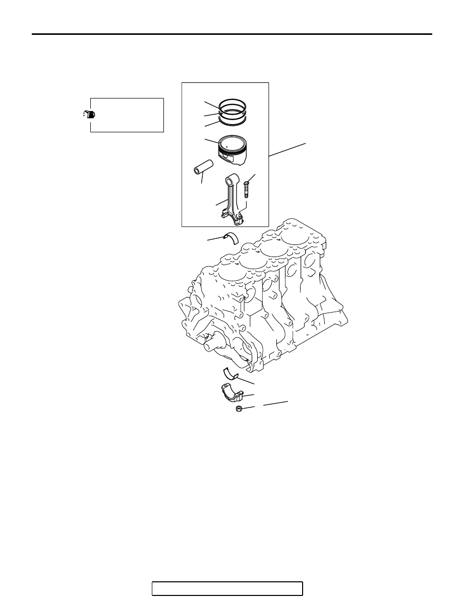
PISTON AND CONNECTING ROD
REMOVAL AND INSTALLATION
M1113008400584
Required Special Tool:
• MIT216941: Piston Pin Setting Tool
AK301260AC
1
2
3
4
5
6
7
8
9
10
11
12
20 ± 2 N·m
15 ± 1 ft-lb
APPLY ENGINE OIL
TO ALL MOVING
PARTS BEFORE
INSTALLATION.
→ + 90˚ to 94˚
REMOVAL STEPS
>>G<<
1. NUT
2. CONNECTING ROD CAP
>>D<<
3. CONNECTING ROD BEARING
>>E<<
4. PISTON AND CONNECTING ROD
ASSEMBLY
>>D<<
5. CONNECTING ROD BEARING
>>C<<
6. PISTON RING No. 1
>>C<<
7. PISTON RING No. 2
>>B<<
8. OIL RING
9. PISTON PIN
10.PISTON
11. CONNECTING ROD
12.BOLT
REMOVAL STEPS (Continued)