Mitsubishi Galant 9G. Manual - part 592


  Index      Mitsubishi     Mitsubishi Galant 9G - service repair manual


Search            


Content   ..  590  591  592  593   ..


Mitsubishi Galant 9G. Manual - part 592


CYLINDER HEAD AND VALVES

TSB Revision

ENGINE OVERHAUL <2.4L ENGINE>

11B-40

3. Before fitting the valve seat, either heat the cylinder head up 

to approximately 250

°C (482°F) or cool the valve seat in 

liquid nitrogen, to prevent the cylinder head bore from 
galling.

4. Using a valve seat cutter, correct the valve seat to the 

specified width and angle. 
See "VALVE SEAT RECONDITIONING PROCEDURE" on 
the previous page.

VALVE GUIDE REPLACEMENT PROCEDURE

1. Using a press, remove the valve guide toward the cylinder 

block.

CAUTION

Do not install a valve guide of the same size again.
2. Rebore the valve guide hole of the cylinder head so that it 

fits the press-fitted oversize valve guide.

Valve guide hole diameters

0.05 oversize 11.05 

 11.07 mm (0.4350  0.4358 inch)

0.25 oversize 11.25 

 11.27 mm (0.4429  0.4437 inch)

0.50 oversize 11.50 

 11.52 mm (0.4528  0.4535 inch)

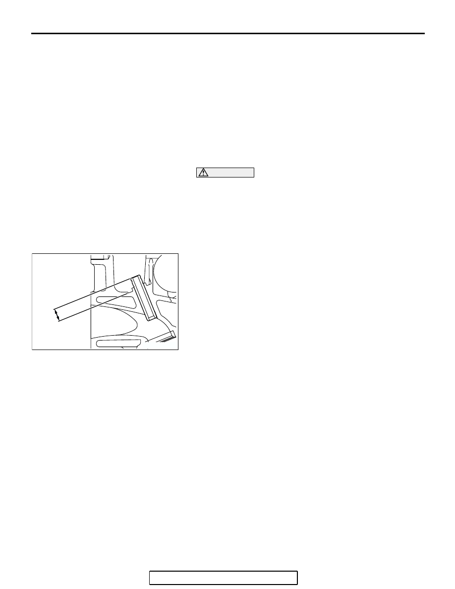
3. Press-fit the valve guide until it protrudes 14.0 mm (0.55 

inch) from the cylinder head top surface as shown in the 
illustration.
NOTE: When press-fitting the valve guide, work from the 
cylinder head top surface.
NOTE: Pay attention to the difference in length of the valve 
guides. [Intake side: 45.5 mm (1.79 inches); exhaust side: 
50.5 mm (1.99 inches)]
NOTE: After installing the valve guides, insert new valves in 
them to check for smooth operation. 

AK301399AC

14.0 mm
(0.55 in)

OIL PAN AND OIL PUMP

TSB Revision

ENGINE OVERHAUL <2.4L ENGINE>

11B-41

OIL PAN AND OIL PUMP

REMOVAL AND INSTALLATION

M1113008100431

AK303217

8

9

10

11

12

13

15

16

17

18

19

20

21

22

23

24

25

26

29

27

28

36 ± 3 N·m
27 ± 1 ft-lb

10 ± 2 N·m
89 ± 17 in-lb

19 ± 3 N·m
14 ± 2 ft-lb

23 ± 3 N·m
17 ± 2 ft-lb

17 ± 1 N·m
12 ± 1 ft-lb

44 ± 5 N·m
33 ± 3 ft-lb

23 ± 3 N·m
17 ± 2 ft-lb

14

APPLY ENGINE OIL
TO ALL MOVING
PARTS BEFORE
INSTALLATION.

2

4

5

6

7

9.0 ± 2.0 N·m
80 ± 17 in-lb

22 ± 4 N·m
17 ± 2 ft-lb

9.0 ± 3.0 N·m
80 ± 26 in-lb

19 ± 3 N·m
14 ± 2 ft-lb

39 ± 5 N·m
29 ± 3 ft-lb

1

3

AB

REMOVAL STEPS

1. DRAIN PLUG

>>M<<

2. DRAIN PLUG GASKET

>>L<<

3. OIL FILTER

<<A>>>K<<

4. OIL PAN
5. BAFFLE PLATE
6. OIL SCREEN
7. OIL SCREEN  GASKET
8. RELIEF PLUG
9. GASKET
10.RELIEF SPRING
11.RELIEF PLUNGER

>>J<<

12.OIL FILTER  BRACKET
13.OIL FILTER BRACKET GASKET

<<B>>>I<<

14.PLUG
15.O-RING

<<C>>>H<<

16.FLANGE BOLT
17.FRONT CASE

18. FRONT CASE GASKET
19. OIL PUMP COVER

>>G<<

20. OIL PUMP DRIVEN GEAR

>>G<<

21. OIL PUMP DRIVE GEAR

>>F<<

22. CRANKSHAFT FRONT OIL SEAL

>>E<<

23. OIL PUMP OIL SEAL

>>D<<

24. COUNTERBALANCE SHAFT OIL 

SEAL

25. COUNTERBALANCE SHAFT, LEFT
26. COUNTERBALANCE SHAFT, RIGHT

<<D>>>C<<

27. COUNTERBALANCE SHAFT, FRONT 

BEARING

<<E>>>B<<

28. COUNTERBALANCE SHAFT, REAR 

BEARING, RIGHT

<<E>>>A<<

29. COUNTERBALANCE SHAFT, REAR 

BEARING, LEFT

REMOVAL STEPS (Continued)

OIL PAN AND OIL PUMP

TSB Revision

ENGINE OVERHAUL <2.4L ENGINE>

11B-42

Required Special Tools:

• MB991603: Bearing Installer Stopper

• MD998162: Plug Wrench

• MD998285: Crankshaft Front Oil Seal Guide

• MD998371: Silent Shaft Bearing Puller

• MD998372: Silent Shaft Bearing Puller

• MD998375: Crankshaft Front Oil Seal Installer

• MD998705: Silent Shaft Bearing Installer

• MD998727: Oil Pan Cutter

• MD998783: Plug Wrench Retainer

REMOVAL SERVICE POINTS

.

<<A>> OIL PAN REMOVAL

1. Remove all oil pan bolts.
2. Drive in special tool MD998727 between the cylinder block 

and oil pan.
NOTE: Never use a screwdriver or chisel to remove the oil 
pan. It will deform the oil pan flange and result in oil leakage.

3. Gently hit the special tool on its corner (shoulder), then slide 

it along the oil pan to remove it.

.

<<B>> PLUG REMOVAL

1. Fit special tool MD998162 on the plug, and then hold it in 

position with special tool MD998783.

2. Loosen the plug.
3. Remove special tools MD998783 and MD998162 and then 

remove the plug.

.

<<C>> FLANGE BOLT REMOVAL

1. Remove the plug on the side of the cylinder block.
2. Insert a Phillips screwdriver [shank diameter 8 mm (0.3 

inch)] into the plug hole to lock the counterbalance shaft.

AK300170

MD998727

AC

AK300171

MD998162

MD998783

AC

AK300172

OIL PAN AND OIL PUMP

TSB Revision

ENGINE OVERHAUL <2.4L ENGINE>

11B-43

3. Loosen the flange bolt.

.

<<D>> COUNTERBALANCE SHAFT FRONT 
BEARING REMOVAL

CAUTION

Be sure to remove the front bearing first. If it has not been 
removed, special tool MD998372 cannot be used for rear 
balance shaft bearing removal.
Using special tool MD998371, remove the counterbalance 
shaft front bearing from the cylinder block.

.

<<E>> COUNTERBALANCE SHAFT REAR 
BEARING REMOVAL

1. Install special tools MB991603 and MD998372 in front of the 

cylinder block when removing the left counterbalance shaft 
rear bearing.

2. Using special tool MD998372, remove the right 

counterbalance shaft rear bearing from the cylinder block.

AK300173

AK300174

MD998371

AC

AK300175AC

MD998372

AK300176

MB991603

MD998372

AC


Content   ..  590  591  592  593   ..