Mitsubishi Galant 9G. Manual - part 558
 

  Index      Mitsubishi     Mitsubishi Galant 9G - service repair manual


Search            


Content   ..  556  557  558  559   ..


Mitsubishi Galant 9G. Manual - part 558


AUTOMATIC TRANSAXLE DIAGNOSIS

TSB Revision

AUTOMATIC TRANSAXLE

23A-310

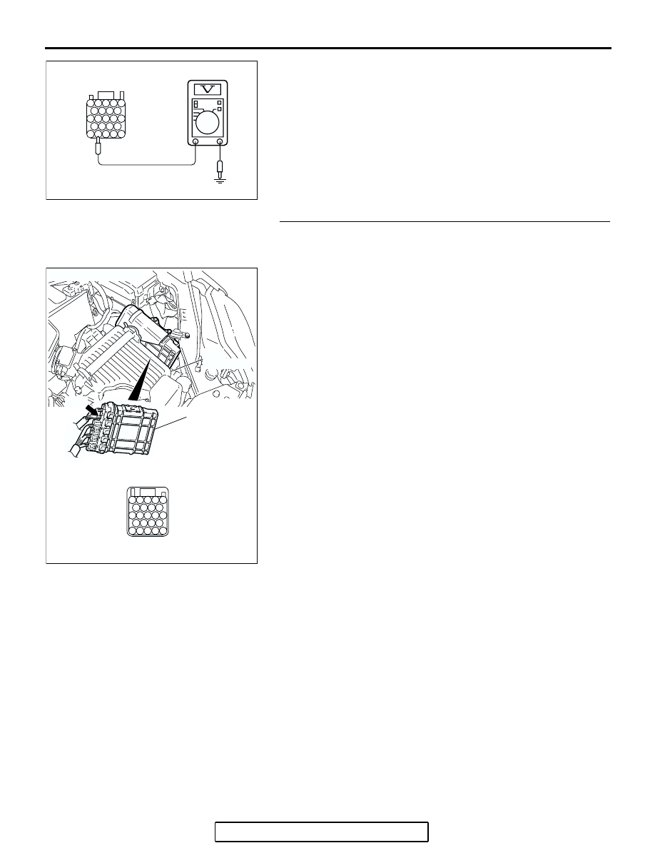
(4) Measure the voltage between terminal 42 and ground.

• The voltage should measure battery positive voltage.

(5) Turn the ignition switch to the "LOCK" (OFF) position.
Q: Is the measured voltage battery positive voltage?

YES : Go to Step 5.
NO :  Go to Step 3.

STEP 3. Check PCM connector B-20 for loose, corroded or 
damaged terminals, or terminals pushed back in the 
connector.
Q: Is the connector in good condition?

YES : Go to Step 4.
NO :  Repair or replace the damaged components. Refer to 

GROUP 00E, Harness Connector Inspection 

P.00E-2

. Then retest the system.

AC210720

24

33

37

42

43

25

34

38

29

40

41

39

21

30

22

23

27

36

32

28

31

35

26

JAE

AC

B-20 HARNESS 
CONNECTOR: 
COMPONENT SIDE

AC306248AH

CONNECTOR: B-20

PCM

AIR
CLEANER

JAE

41

37

32

40

39

23

21 22

35

31

30

26

36

27

43

42

25

24

38

34

29

33

28

B-20

AUTOMATIC TRANSAXLE DIAGNOSIS

TSB Revision

AUTOMATIC TRANSAXLE

23A-311

STEP 4. Check the harness for open circuit between PCM 
connector B-20 terminal 42 and battery.
Q: Is the harness wire in good condition?

YES : Go to Step 5.
NO :  Repair or replace the harness wire.

STEP 5. Using scan tool MB991958, check data list item 61: 
Transmission Range Switch.

CAUTION

To prevent damage to scan tool MB991958, always turn the 
ignition switch to the "LOCK" (OFF) position before con-
necting or disconnecting scan tool MB991958.
(1) Connect scan tool MB991958 to the data link connector.
(2) Turn the ignition switch to the "ON" position.
(3) Set scan tool MB991958 to the data reading mode.

• Item 61: Transmission Range Switch.

• Move the selector lever to "P," "R," "N," "D" positions 

and confirm that the selected transmission range 
match the positions shown on scan tool MB991958.

(4) Turn the ignition switch to the "LOCK" (OFF) position.
Q: Is the switch operating properly?

YES : Check for the symptom. If the symptom is not 

eliminated, replace the PCM.

NO :  Refer to 

P.23A-120

P.23A-165

, DTCs 27, 28: 

Transmission Range Switch system.

AC306248AH

CONNECTOR: B-20

PCM

AIR
CLEANER

JAE

41

37

32

40

39

23

21 22

35

31

30

26

36

27

43

42

25

24

38

34

29

33

28

B-20

AC305412

AB

MB991910

DATA LINK

CONNECTOR

MB991824

MB991827

AUTOMATIC TRANSAXLE DIAGNOSIS

TSB Revision

AUTOMATIC TRANSAXLE

23A-312

INSPECTION PROCEDURE 13: Poor Acceleration

.

COMMENT

If acceleration is poor when downshifting occurs 
while driving, a malfunction of the engine system or a 
brake or clutch may exist.

.

TROUBLESHOOTING HINTS (The most 
likely causes for this condition:)

• Malfunction of the engine system

• Malfunction of the clutch system and brake sys-

tem

• Malfunction of the PCM

DIAGNOSIS

STEP 1. Check the engine system.
Refer to GROUP 13A <2.4L Engine>, Diagnosis 

− Symptom 

Chart 

− Poor acceleration 

P.13A-1015

.

Refer to GROUP 13B <3.8L Engine>, Diagnosis 

− Symptom 

Chart 

− Poor acceleration 

P.13B-1066

.

Q: Is the inspection result good?

YES : Go to Step 2.
NO :  Repair or replace the engine component(s).

STEP 2. Check each brake and clutch.
Perform the torque converter stall test. Refer to 

P.23A-28

Torque Converter Stall Test. Then retest the system.
Q: Is the symptom eliminated?

YES : The procedure is complete.
NO :  Go to Step 3.

STEP 3. Perform the hydraulic pressure test.
Perform the hydraulic pressure test. Refer to 

P.23A-29

Hydraulic Pressure Test. Then retest the system.
Q: Is the symptom eliminated?

YES : The procedure is complete.
NO :  Go to Step 4.

AUTOMATIC TRANSAXLE DIAGNOSIS

TSB Revision

AUTOMATIC TRANSAXLE

23A-313

STEP 4. Check each brake system and each clutch system.
(1) Remove the valve body cover and valve body. Refer to 

GROUP 23B, Transaxle 

P.23B-10

.

(2) Blow 108 kPa (15 psi) compressed air into the each brake 

oil orifice and clutch oil orifice of the transaxle case, and 
check if each brake and each clutch piston move and air 
pressure is maintained.

Q: Is the air pressure maintained?

YES : The procedure is complete.
NO :  Go to Step 5.

STEP 5. Check each brake system and clutch system.
(1) Remove the transaxle.
(2) Check the facings for seizure and piston seal ring for 

damage and interference with retainer. Repair or replace 
the faulty parts. Refer to GROUP 23B, Transaxle 

P.23B-10

Underdrive Clutch and Input Shaft 

P.23B-60

, Reverse and 

Overdrive Clutch 

P.23B-62

. Then retest the system.

Q: Is the symptom eliminated?

YES : The procedure is complete.
NO :  Go to Step 6.

STEP 6. Replace the PCM.
Q: Is the symptom eliminated?

YES : The procedure is complete.
NO :  Start over at Step 1.

AC001870

LOW-REVERSE BRAKE
OIL ORIFICE

REVERSE CLUTCH
OIL ORIFICE

OVERDRIVE
CLUTCH
OIL ORIFICE

SECOND BRAKE
OIL ORIFICE

UNDERDRIVE
CLUTCH
OIL ORIFICE

AB

AC001868

REVERSE
CLUTCH

SECOND
BRAKE

LOW-
REVERSE
BRAKE

UNDERDRIVE
CLUTCH

OVERDRIVE CLUTCH

AB


Content   ..  556  557  558  559   ..