Mitsubishi Galant 9G. Manual - part 556


  Index      Mitsubishi     Mitsubishi Galant 9G - service repair manual


Search            


Content   ..  554  555  556  557   ..


Mitsubishi Galant 9G. Manual - part 556


AUTOMATIC TRANSAXLE DIAGNOSIS

TSB Revision

AUTOMATIC TRANSAXLE

23A-302

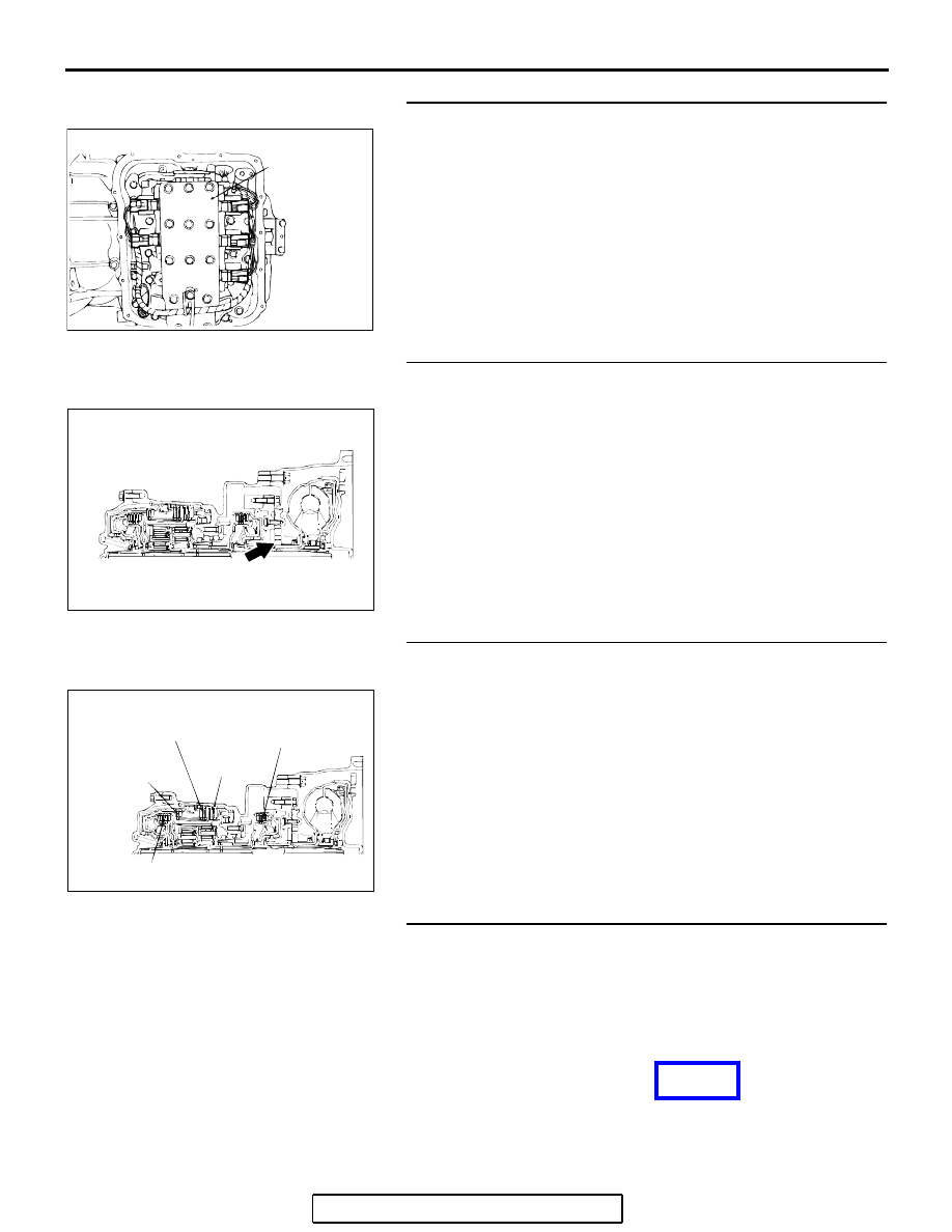
STEP 4. Disassemble and clean the valve body.
Check the O-ring installation bolts for looseness and the valve 
body for damage. Repair or replace the faulty parts. Refer to 
GROUP 23B, Valve Body 

P.23B-80

.

Replace the valve body assembly if the damages are thought 
to be irreparable. Then check the symptom.
Q: Is the symptom eliminated?

YES : The procedure is complete.
NO :  Go to Step 5.

STEP 5. Check the oil pump.
(1) Remove the transaxle.
(2) Check the oil pump (incorrect installation, damage and etc.) 

and replace the oil pump assembly if necessary (The oil 
pump cannot be disassembly).Refer to GROUP 23B, 
Transaxl

P.23B-10

. Confirm that the malfunction symptom 

is eliminated.

Q: Is the symptom eliminated?

YES : The procedure is complete.
NO :  Go to Step 7.

STEP 6. Check each brake and clutch.
(1) Remove the transaxle.
(2) Check the facing for seizure and piston seal ring for 

damage and interference with retainer. Repair or replace 
the faulty parts. Refer to GROUP 23B, Transaxle 

P.23B-10

Underdrive Clutch and Input Shaft 

P.23B-60

, Reverse and 

Overdrive Clutch 

P.23B-62

. Then Retest the system.

Q: Is the symptom eliminated?

YES : The procedure is complete.
NO :  Go to Step 7.

STEP 7. Replace the PCM.
Q: Is the symptom eliminated?

YES : The procedure is complete.
NO :  Start over at Step 1.

AC001860 AB

VALVE
BODY
ASSEMBLY

AC001865

AC001868

REVERSE
CLUTCH

SECOND
BRAKE

LOW-
REVERSE
BRAKE

UNDERDRIVE
CLUTCH

OVERDRIVE CLUTCH

AB

NEXT>>

AUTOMATIC TRANSAXLE DIAGNOSIS

TSB Revision

AUTOMATIC TRANSAXLE

23A-303

23A

INSPECTION PROCEDURE 10: Early or Late Shifting in All Gears

.

COMMENT

If all shift points are early or late while driving, the 
cause is probably a malfunction of the output shaft 
speed sensor, TP sensor or a solenoid valve.

.

TROUBLESHOOTING HINTS (The most 
likely causes for this condition:)

• Malfunction of the output shaft speed sensor

• Malfunction of the TP sensor

• Malfunction of each solenoid valve

• Abnormal line pressure

• Malfunction of the valve body

• Malfunction of the PCM

DIAGNOSIS

Required Special Tool:

• MB991958: Scan Tool (MUT-III Sub Assembly)

• MB991824: V.C.I.

• MB991827: MUT-III USB Cable

• MB991910: MUT-III Main Harness A

STEP 1. Using scan tool MB991958, check data list item 23: 
Output Shaft Speed Sensor.

CAUTION

To prevent damage to scan tool MB991958, always turn the 
ignition switch to the "LOCK" (OFF) position before con-
necting or disconnecting scan tool MB991958. 
(1) Connect scan tool MB991958 to the data link connector.
(2) Start the engine.
(3) Set scan tool MB991958 to the data reading mode.

• Item 23: Output Shaft Speed Sensor.

• When driving at constant speed of 50km/h (31mph), 

the display should be "1,400 

− 1,700 r/min" (Gear 

range: 3rd gear).

(4) Turn the ignition switch to the "LOCK" (OFF) position.
Q: Is the sensor operating properly?

YES : Go to Step 2.
NO :  Refer to 

P.23A-90

, DTC 23: Output shaft speed 

sensor system.

AC305412

AB

MB991910

DATA LINK

CONNECTOR

MB991824

MB991827

<<PREVIOUS

AUTOMATIC TRANSAXLE DIAGNOSIS

TSB Revision

AUTOMATIC TRANSAXLE

23A-304

STEP 2. Using scan tool MB991958, check data list item 11: 
TP Sensor.
(1) Connect scan tool MB991958 to the data link connector.
(2) Turn the ignition switch to the "ON" position.
(3) Set scan tool MB991958 to the data reading mode.

• Item 11: TP Sensor.

• With the throttle valve in idle position, voltage should 

measure between 300 and 700 mV.

• With the throttle valve in full-open position, voltage 

should measure 4,000 mV or more.

(4) Turn the ignition switch to the "LOCK" (OFF) position.
Q: Is the measured voltage between 300 and 700 mV at 

idle, and 4,000 mV or more at the full-open position?
YES : 
Go to Step 3.
NO :  Check the TP sensor. Refer to GROUP13A <2.4L 

Engine>, Diagnostic Trouble Code Procedures 

P.13A-159

P.13A-169

, DTCs P0122, P0123: TP 

Sensor System or refer to GROUP13B <3.8L 
Engine>, Diagnostic Trouble Code Procedures 

P.13B-162

P.13B-172

, DTCs P0122, P0123: TP 

Sensor System. Then check the symptom.

STEP 3. Using scan tool MB991958, check data list.
(1) Connect scan tool MB991958 to the data link connector.
(2) Start the engine.
(3) Set scan tool MB991958 to the data reading mode for 

following items.

a. Item 31: Low-Reverse Solenoid Valve Duty Percent
b. Item 32: Underdrive Solenoid Valve Duty Percent

c. Item 33: Second Solenoid Valve Duty Percent

d. Item 34: Overdrive Solenoid Valve Duty Percent

• Check that the values shown below are displayed 

when each data list item is entered.

AC305412

AB

MB991910

DATA LINK

CONNECTOR

MB991824

MB991827

AC305412

AB

MB991910

DATA LINK

CONNECTOR

MB991824

MB991827

DRIVING CONDITION

DATA LIST ITEM
31

32

33

34

Driving at constant speed of 10 km/h (6.2 mph) in 1st gear 0%

0%

100%

100%

Driving at constant speed of 30 km/h (19 mph) in 2nd gear 100%

0%

0%

100%

Driving at constant speed of 50 km/h (31 mph) in 3rd gear 100%

0%

100%

0%

Driving at constant speed of 50 km/h (31 mph) in 4th gear 100%

100%

0%

0%

AUTOMATIC TRANSAXLE DIAGNOSIS

TSB Revision

AUTOMATIC TRANSAXLE

23A-305

(4) Turn the ignition switch to the "LOCK" (OFF) position.
Q: Are the solenoid valves operating properly?

YES : Go to Step 4.
NO :  Go to Step 6.

STEP 4. Adjust the line pressure.
Adjust the line pressure. Refer to 

P.23A-42

, Line Pressure 

Adjustment. Then check the symptom.
Q: Is the symptom eliminated?

YES : The procedure is complete.
NO :  Go to Step 5.

STEP 5. Disassemble and clean the valve body.
Check the O-ring installation bolts for looseness and the valve 
body for damage. Repair or replace the faulty parts. Refer to 
GROUP 23B, Valve Body 

P.23B-80

.

Replace the valve body assembly if the damages are thought 
to be irreparable. Then check the symptom.
Q: Is the symptom eliminated?

YES : The procedure is complete.
NO :  Go to Step 7.

STEP 6. Replace each solenoid valve.
Replace the faulty solenoid valve with a new one.
Q: Is the symptom eliminated?

YES : The procedure is complete.
NO :  Go to Step 7.

STEP 7. Replace the PCM.
Q: Is the symptom eliminated?

YES : The procedure is complete.
NO :  Start over at Step 1.

INSPECTION PROCEDURE 11: Early or Late Shifting in Some Gears

.

COMMENT

If some of the shift points are early or late when driv-
ing, the cause is probably a malfunction of the valve 
body, or it is due to the characteristics of the 
INVECS-II system but is not an abnormality.

.

TROUBLESHOOTING HINTS (The most 
likely causes for this condition:)

• Malfunction of the valve body

• Malfunction of the PCM

AC001860 AB

VALVE
BODY
ASSEMBLY

AC001869 AB

OVERDRIVE
SOLENOID
VALVE

LOW-
REVERSE
SOLENOID
VALVE

VALVE
BODY
ASSEMBLY

UNDERDRIVE
SOLENOID
VALVE

SECOND
SOLENOID
VALVE


Content   ..  554  555  556  557   ..