Mitsubishi Galant 9G. Manual - part 507


  Index      Mitsubishi     Mitsubishi Galant 9G - service repair manual


Search            


Content   ..  505  506  507  508   ..


Mitsubishi Galant 9G. Manual - part 507


AUTOMATIC TRANSAXLE DIAGNOSIS

TSB Revision

AUTOMATIC TRANSAXLE

23A-106

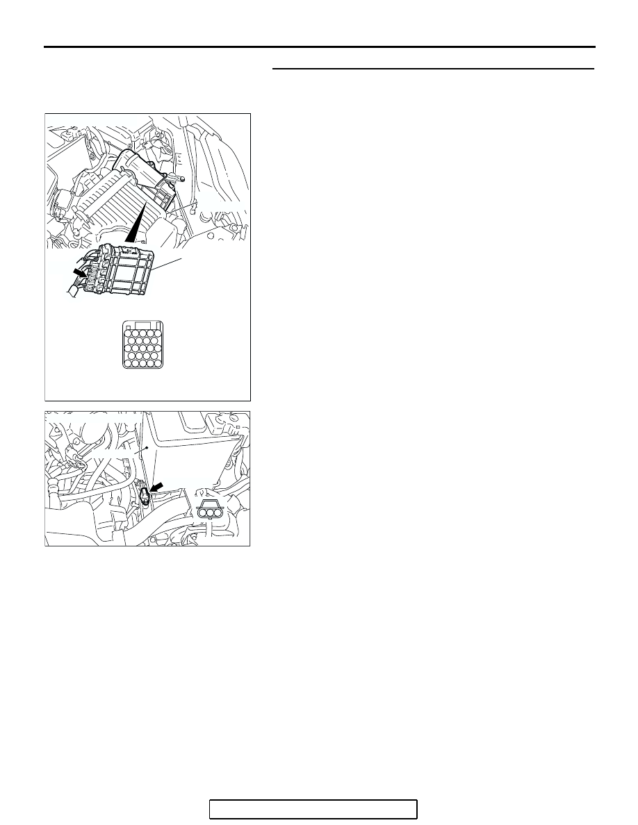
STEP 14. Check the harness for open circuit or damage 
between PCM connector B-22 terminal 113 and output 
shaft speed sensor connector B-107 terminal 1.
Q: Is the harness wire in good condition?

YES : Go to Step 16.
NO :  Repair or replace the harness wire.

AC306248AE

B-22 
(B)

CONNECTOR: B-22

PCM

AIR
CLEANER

JAE

94

98

107

103

112

91

100

109

101102

106

110

105

111

97

92

96

93

104

113

108

95

99

AC305353AC

CONNECTOR: B-107

BATTERY

B-107 (GR)

3

2

1

AUTOMATIC TRANSAXLE DIAGNOSIS

TSB Revision

AUTOMATIC TRANSAXLE

23A-107

STEP 15. Check PCM connector B-22 for loose, corroded 
or damaged terminals, or terminals pushed back in the 
connector.
Q: Are the connector and terminals in good condition?

YES : Replace the PCM.
NO :  Repair or replace the damaged components. Refer to 

GROUP 00E, Harness Connector Inspection 

P.00E-2

.

AC306248AE

B-22 
(B)

CONNECTOR: B-22

PCM

AIR
CLEANER

JAE

94

98

107

103

112

91

100

109

101102

106

110

105

111

97

92

96

93

104

113

108

95

99

AUTOMATIC TRANSAXLE DIAGNOSIS

TSB Revision

AUTOMATIC TRANSAXLE

23A-108

STEP 16. Using the oscilloscope, check the output shaft 
speed sensor waveform at PCM connectors B-22 by using 
check harness special tool MB991923.
(1) Disconnect all the connectors from the PCM.

(2) Connect special tool MB991923 (check harness) between 

the PCM and the body-side harness connector.

AC306248AE

B-22 
(B)

CONNECTOR: B-22

PCM

AIR
CLEANER

JAE

94

98

107

103

112

91

100

109

101102

106

110

105

111

97

92

96

93

104

113

108

95

99

AC209793AH

SPECIAL TOOL 23-PIN CONNECTOR
WITH RED TAPE
(PCM CONNECTOR B-22)

104

96

94

95

93 92 91

99 98 97

103 102 101 100

108 107 106 105

113 112 111 110 109

PCM

MB991923

BODY SIDE
HARNESS

B-22
(GR)

AUTOMATIC TRANSAXLE DIAGNOSIS

TSB Revision

AUTOMATIC TRANSAXLE

23A-109

(3) Connect an oscilloscope probe to PCM connector B-22 

terminal 112 and 113.

(4) Start the engine and drive the vehicle at constant speed of 

50 km/h (31 mph) (Gear range: 3rd gear).

(5) Check the output shaft speed sensor waveform.

• The output shaft speed sensor waveform should show a 

pattern similar to the illustration. The maximum value 
should be 4.8 volts or more and the minimum value 0.8 
volt or less. The output waveform should not contain 
electrical noise.

(6) Turn the ignition switch to the "LOCK" (OFF) position.
Q: Is the waveform normal?

YES : Go to Step 19.
NO :  Go to Step 17.

STEP 17. Replace the output shaft speed sensor.
(1) Replace the output shaft speed sensor. Refer to GROUP 

23B, Transaxle 

P.23B-10

.

(2) Test drive the vehicle.
(3) Check for A/T diagnostic trouble code.
Q: Is A/T DTC 23 set?

YES : Go to Step 18.
NO :  The procedure is complete.

STEP 18. Replace the transfer drive gear or driven gear.
(1) Replace the transfer drive gear or driven gear. Refer to 

GROUP 23B, Transaxle 

P.23B-10

, Output Shaft 

P.23B-73

.

(2) Test drive the vehicle.
(3) Check for A/T diagnostic trouble code.
Q: Is A/T DTC 23 set?

YES : An A/T DTC may have set due to external radio 

frequency interference (RFI) possibility caused by 
cellular phone activity, or aftermarket components 
installed on the vehicle.

NO :  The procedure is complete.

AC210429

JAE

94

98

107

103

112

91

100

109

101

102

106

110

105

111

97

92

96

93

104

113

108

95

99

AC

B-22 CONNECTOR: 
COMPONENT
SIDE VIEW

OSCILLO-
SCOPE

PROBE

ACX02131

NORMAL WAVEFORM

AD

(V)

5

0

AC305353AD

OUTPUT SHAFT
SPEEDB SENSOR

BATTERY

AC002221AC

TRANSFER
DRIVE GEAR

TRANSFER
DRIVEN GEAR


Content   ..  505  506  507  508   ..