Mitsubishi Galant 9G. Manual - part 484


  Index      Mitsubishi     Mitsubishi Galant 9G - service repair manual


Search            


Content   ..  482  483  484  485   ..


Mitsubishi Galant 9G. Manual - part 484


AUTOMATIC TRANSAXLE DIAGNOSIS

TSB Revision

AUTOMATIC TRANSAXLE

23A-14

AUTOMATIC TRANSAXLE DIAGNOSIS

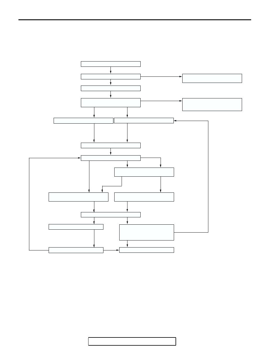
DIAGNOSTIC TROUBLESHOOTING FLOW

M1231013500353

INTRODUCTION TO A/T DIAGNOSIS

M1231012300226

The automatic transaxle can exhibit any of the follow-
ing symptoms: noise or vibration is generated, Trans-
mission fluid leaks, the vehicle does not move 
forward or backward. The causes of these symptoms 
could come from: Incorrect mounting, the Transmis-
sion fluid may be low, or a component of the tran-
saxle may be faulty. 

The following items are suspected as causes for the 
INVECS-II troubles: malfunction of the PCM, the 
sensors, the switches, the harness or connectors.


Gather information from customer.

Check the  transmission fluid.

Verify complaint.

Replace or replenish the
transmission fluid.

Communication with the scan tool
MB991958 (MUT-III sub assembly)
not possible in Symptom Chart.

Read the diagnostic trouble code.

Erase the diagnostic trouble code.

Check symptom.

Perform the repair.

Road test

Recheck diagnostic trouble codes 
which were read before road test.

To DIAGNOSTIC TROUBLE CODE 
CHART

To SYMPTOM CHART

Search for cause.

Repair

Confirmation test (road test)

INTERMITTENT MALFUNCTIONS
(Refer to GROUP 00, How to Use
Troubleshooting/Inspection 
Service Points.)

Completed

NG

OK

Communication with the scan tool
MB991958 (MUT-III sub assembly)
not possible

Diagnostic trouble code
displayed.

No diagnostic trouble code
displayed.

Abnormality exists (no diagnostic 
trouble code)

Abnormality exists 
(diagnostic trouble 
code present)

No abnormality

No diagnostic trouble code
displayed.

Diagnostic trouble code
displayed.

Found

Not found

OK

OK

NG

AC210189

NG

AB

AUTOMATIC TRANSAXLE DIAGNOSIS

TSB Revision

AUTOMATIC TRANSAXLE

23A-15

A/T DIAGNOSTIC TROUBLESHOOTING STRATEGY

M1231007600339

Use these steps to plan your diagnostic strategy. If 
you follow them carefully, you will find most A/T mal-
functions.
1. Gather as much information as possible about the 

complaint from the customer.

2. Verify that the condition described by the 

customer exists.

3. Check the vehicle for any A/T Diagnostic Trouble 

Codes (DTCs).

4. If you can not verify the condition and there are no 

DTCs, the malfunction is intermittent. For 
information on how to cope with intermittent 
malfunctions, refer to GROUP 00, How to Use 
Troubleshooting/Inspection Service Points 

− How 

to Cope with Intermittent Malfunction 

P.00-14

.

5. If you can verify the condition but there are no 

DTCs, or the system can not communicate with 
scan tool, refer to the Symptom Chart 

P.23A-44

.

6. If there is a DTC, record the number of the code, 

then erase the code from memory using scan tool.

7. Reconfirm the symptom with a Road Test.
8. If a DTC is set again, go to the Inspection Chart 

for Diagnostic Trouble Codes.

9. If a DTC is not set again, the malfunction is 

intermittent. For information on how to cope with 
intermittent malfunctions, refer to GROUP 00, 
How to Use Troubleshooting/Inspection Service 
Points 

− How to Cope with Intermittent 

Malfunction 

P.00-14

.

10.After repairs are completed, conduct a Road Test 

duplicating the complaint conditions to confirm the 
malfunction has been eliminated.

DIAGNOSTIC FUNCTION

M1231022500135

CHECK "N" RANGE  LIGHT

The "N" range light flashes once per second if there is an 
abnormality in any of the items in the table below which are 
related to the A/T system. Check for diagnostic trouble codes if 
the "N" range light is flashing once per second. 

"N" range light flashing items

• Input shaft speed sensor

• Output shaft speed sensor

• Each solenoid valve

• Gear incorrect ratio

• A/T control relay system

CAUTION

If the "N" range light is  flashing, the transmission fluid 
temperature is high. (It flushes when the fluid is approxi-
mately 125

°C or more and goes off when the fluid is 

approximately 115

°C or less)

ON-BOARD DIAGNOSTICS

The powertrain control module (PCM) monitors its 
input/output signals (some signals all the time and 
others under specified conditions). When an irregular 
signal is initially monitored, the PCM decides that a 
malfunction has occurred and records the occur-
rence as a diagnostic trouble code. There are 21 
diagnostic items. The diagnostic results can be read 
with scan tool. Diagnostic trouble codes are kept in 
memory by direct battery feed. The codes are 

retained in memory even if the ignition switch is in 
the "LOCK" (OFF) position. DTCs are not erased 
even after the battery terminals and the PCM con-
nector are disconnected. In addition, the diagnostic 
trouble code can also be erased by scan tool.
NOTE: If a sensor is disconnected when the ignition 
switch is in the "ON" position, a diagnostic trouble 
code is stored in memory. In this case, erase the 
DTC using scan tool.
The 21 diagnostic items are displayed in numeric 
order.

AC209439AC

AUTOMATIC TRANSAXLE DIAGNOSIS

TSB Revision

AUTOMATIC TRANSAXLE

23A-16

HOW TO CONNECT THE SCAN TOOL (MUT-III)

Required Special Tools:

•  MB991958: Scan Tool (MUT-III Sub Assembly)

• MB991824: Vehicle Communication Interface (V.C.I.)

• MB991827: MUT-III USB Cable

• MB991910: MUT-III Main Harness A

CAUTION

To prevent damage to scan tool MB991958, always turn the 
ignition switch to the "LOCK" (OFF) position before con-
necting or disconnecting scan tool MB991958.
1. Ensure that the ignition switch is at the "LOCK" (OFF) 

position.

2. Start up the personal computer.
3. Connect special tool MB991827 to special tool MB991824 

and the personal computer.

4. Connect special tool MB991910 to special tool MB991824.
5. Connect special tool MB991910 to the data link connector.
6. Turn the power switch of special tool MB991824 to the "ON" 

position.
NOTE: When special tool MB991824 is energized, special 
tool MB991824 indicator light will be illuminated in a green 
color.

7. Start the MUT-III system on the personal computer.
NOTE: Disconnecting scan tool MB991958 is the reverse of the 
connecting sequence, making sure that the ignition switch is at 
the "LOCK" (OFF) position.

HOW TO READ AND ERASE DIAGNOSTIC 
TROUBLE CODES

Required Special Tools:

•  MB991958: Scan Tool (MUT-III Sub Assembly)

• MB991824: V.C.I.

• MB991827: MUT-III USB Cable

• MB991910: MUT-III Main Harness A

AC305412

AB

MB991910

DATA LINK

CONNECTOR

MB991824

MB991827

AUTOMATIC TRANSAXLE DIAGNOSIS

TSB Revision

AUTOMATIC TRANSAXLE

23A-17

CAUTION

To prevent damage to scan tool MB991958, always turn the 
ignition switch to the "LOCK" (OFF) position before con-
necting or disconnecting scan tool MB991958.

NOTE: If the battery voltage is low, diagnostic trouble codes 
will not be set. Check the battery if scan tool MB991958 
does not display.

1. Connect scan tool MB991958 to the data link connector.
2. Turn the ignition switch to the "ON" position.
3. Select "Interactive Diagnosis" from the start-up screen.
4. Select "System select."
5. Choose "ELC-A/T" from the "POWER TRAIN" tab.
6. Select "MITSUBISHI."
7. Select "Diagnostic Trouble Code."
8. If a DTC is set, it is shown.
9. Choose "Erase DTCs" to erase the DTC.

HOW TO READ DATA LIST

Required Special Tools:

•  MB991958 : Scan Tool (MUT-III Sub Assembly)

• MB991824: V.C.I.

• MB991827: MUT-III USB Cable

• MB991910: MUT-III Main Harness A

CAUTION

To prevent damage to scan tool MB991958, always turn the 
ignition switch to the "LOCK" (OFF) position before con-
necting or disconnecting scan tool MB991958.
1. Connect scan tool MB991958 to the data link connector.
2. Turn the ignition switch to the "ON" position.
3. Select "Interactive Diagnosis" from the start-up screen.
4. Select "System select."
5. Choose "ELC-A/T" from the "POWER TRAIN" tab.
6. Select "MITSUBISHI."
7. Select "Data List."
8. Choose an appropriate item and select the "OK" button.

AC305412

AB

MB991910

DATA LINK

CONNECTOR

MB991824

MB991827

AC305412

AB

MB991910

DATA LINK

CONNECTOR

MB991824

MB991827


Content   ..  482  483  484  485   ..