Mitsubishi Galant 9G. Manual - part 455


  Index      Mitsubishi     Mitsubishi Galant 9G - service repair manual


Search            


Content   ..  453  454  455  456   ..


Mitsubishi Galant 9G. Manual - part 455


AUTO-CRUISE CONTROL

TSB Revision

ENGINE AND EMISSION CONTROL

17-38

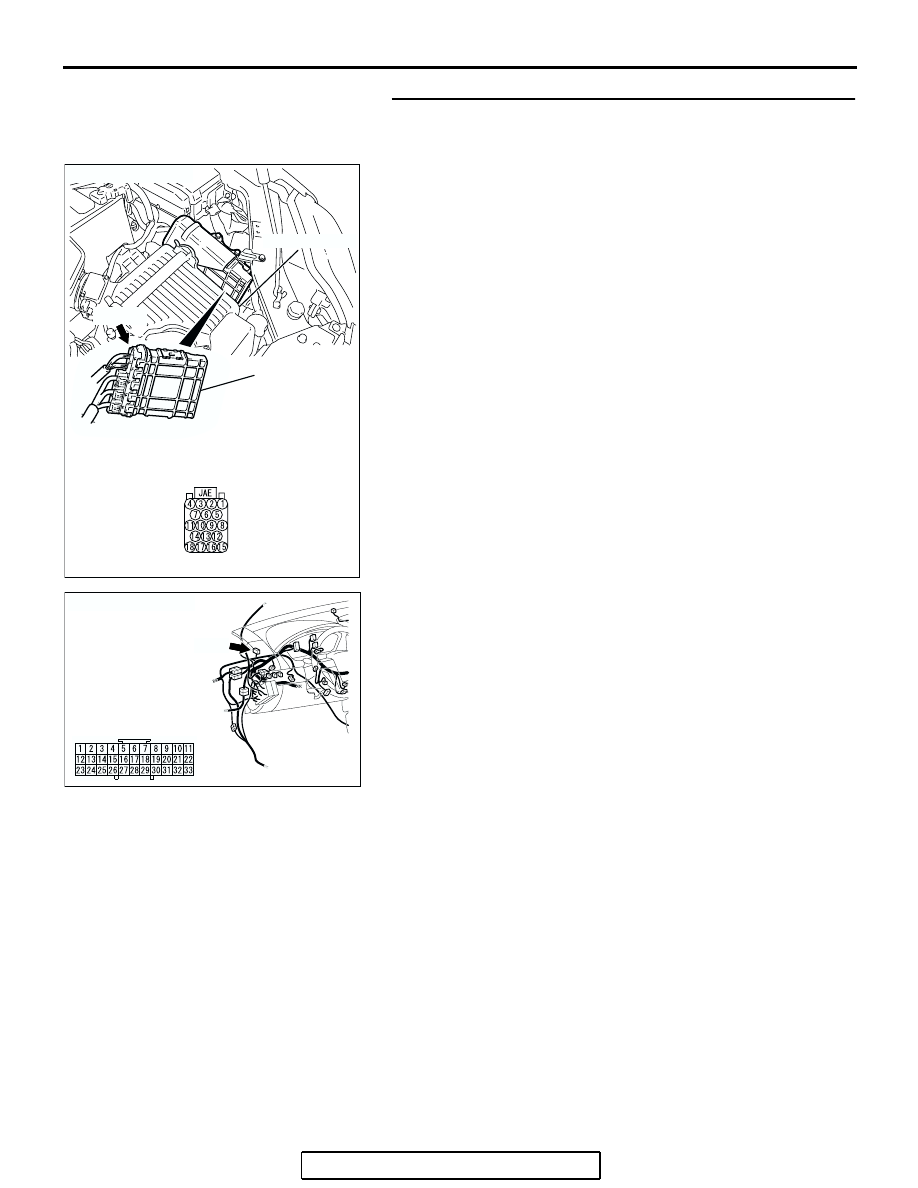
STEP 4. Check PCM connector B-19 and joint connector 
(1) C-01 for loose, corroded or damaged terminals, or 
terminals pushed back in the connector.
Q: Are the connectors and terminals in good condition?

YES : Go to Step 5.
NO :  Repair or replace the damaged components. (Refer to 

GROUP 00E, Harness Connector Inspection 

P.00E-2

). Then go to Step 22.

AC305710

B-19 HARNESS

CONNECTOR:

COMPONENT SIDE

AC

B-19 (B)

CONNECTOR: B-19

AIR CLEANER

PCM

AC305231AN

CONNECTOR: C-01

C-01 

C-01 HARNESS
CONNECTOR:
COMPONENT SIDE

AUTO-CRUISE CONTROL

TSB Revision

ENGINE AND EMISSION CONTROL

17-39

STEP 5. Check the harness wire between PCM connector 
B-19 terminal 9 and joint connector (1) C-01 terminal 14 for 
damage.
Q: Is the harness wire in good condition?

YES : Go to Step 13.
NO :  Repair the damaged harness wire. Then go to Step 

22.

AC305710

B-19 HARNESS

CONNECTOR:

COMPONENT SIDE

AC

B-19 (B)

CONNECTOR: B-19

AIR CLEANER

PCM

AC305231AN

CONNECTOR: C-01

C-01 

C-01 HARNESS
CONNECTOR:
COMPONENT SIDE

AUTO-CRUISE CONTROL

TSB Revision

ENGINE AND EMISSION CONTROL

17-40

STEP 6. Measure the power supply voltage at stoplight 
switch connector C-30 by backprobing.
(1) Disconnect stoplight switch connector C-30.

(2) Measure the power supply voltage between stoplight switch 

connector C-30 terminal 2 and ground.

(3) Reconnect stoplight switch connector C-30.
Q: Is the measured voltage battery positive voltage 

(approximately 12 volts)?
YES : 
Go to Step 10.
NO :  Go to Step 7.

STEP 7. Check stoplight switch connector C-30 for loose, 
corroded or damaged terminals, or terminals pushed back 
in the connector.
Q: Are the connector and terminals in good condition?

YES : Go to Step 8.
NO :  Repair or replace the damaged components. (Refer to 

GROUP 00E, Harness Connector Inspection 

P.00E-2

). Then go to Step 22.

AC305231AO

CONNECTOR: C-30

C-30

C-30 HARNESS
CONNECTOR:
COMPONENT SIDE

AC305712AB

C-30 HARNESS
CONNECTOR:
COMPONENT SIDE

AC305231AO

CONNECTOR: C-30

C-30

C-30 HARNESS
CONNECTOR:
COMPONENT SIDE

AUTO-CRUISE CONTROL

TSB Revision

ENGINE AND EMISSION CONTROL

17-41

STEP 8. Check the harness wire between stoplight switch 
connector C-30 terminal 2 and fuse number 11 at the relay 
box at engine compartment for damage.
Q: Is the harness wire in good condition?

YES : Go to Step 9.
NO :  Repair the damaged harness wire. Then go to Step 

22.

STEP 9. Check the fuse number 11 at the relay box at 
engine compartment.
Q: Is the fuse in good condition?

YES : Go to Step 10.
NO :  Check the stoplight system harness and replace the 

fuse. Then go to Step 22.

AC305231AO

CONNECTOR: C-30

C-30

C-30 HARNESS
CONNECTOR:
COMPONENT SIDE

AC305713AB

BATTERY

RELAY BOX

FUSE NUMBER 11
(HOUSING COLOR:
BLUE)

AC305713AB

BATTERY

RELAY BOX

FUSE NUMBER 11
(HOUSING COLOR:
BLUE)


Content   ..  453  454  455  456   ..