Mitsubishi Galant 9G. Manual - part 453


  Index      Mitsubishi     Mitsubishi Galant 9G - service repair manual


Search            


Content   ..  451  452  453  454   ..


Mitsubishi Galant 9G. Manual - part 453


AUTO-CRUISE CONTROL

TSB Revision

ENGINE AND EMISSION CONTROL

17-30

STEP 15. Check auto-cruise control switch connector 
C-302 for loose, corroded or damaged terminals, or 
terminals pushed back in the connector.
Q: Are the connector and terminals in good condition?

YES : Go to Step 16.
NO :  Repair or replace the faulty connector. (Refer to 

GROUP 00E, Harness Connector Inspection 

P.00E-2

). Install the air bag module (driver’s side). 

(Refer to GROUP 52B, Air Bag Modules and Clock 
Spring 

P.52B-369

). Then go to Step 18.

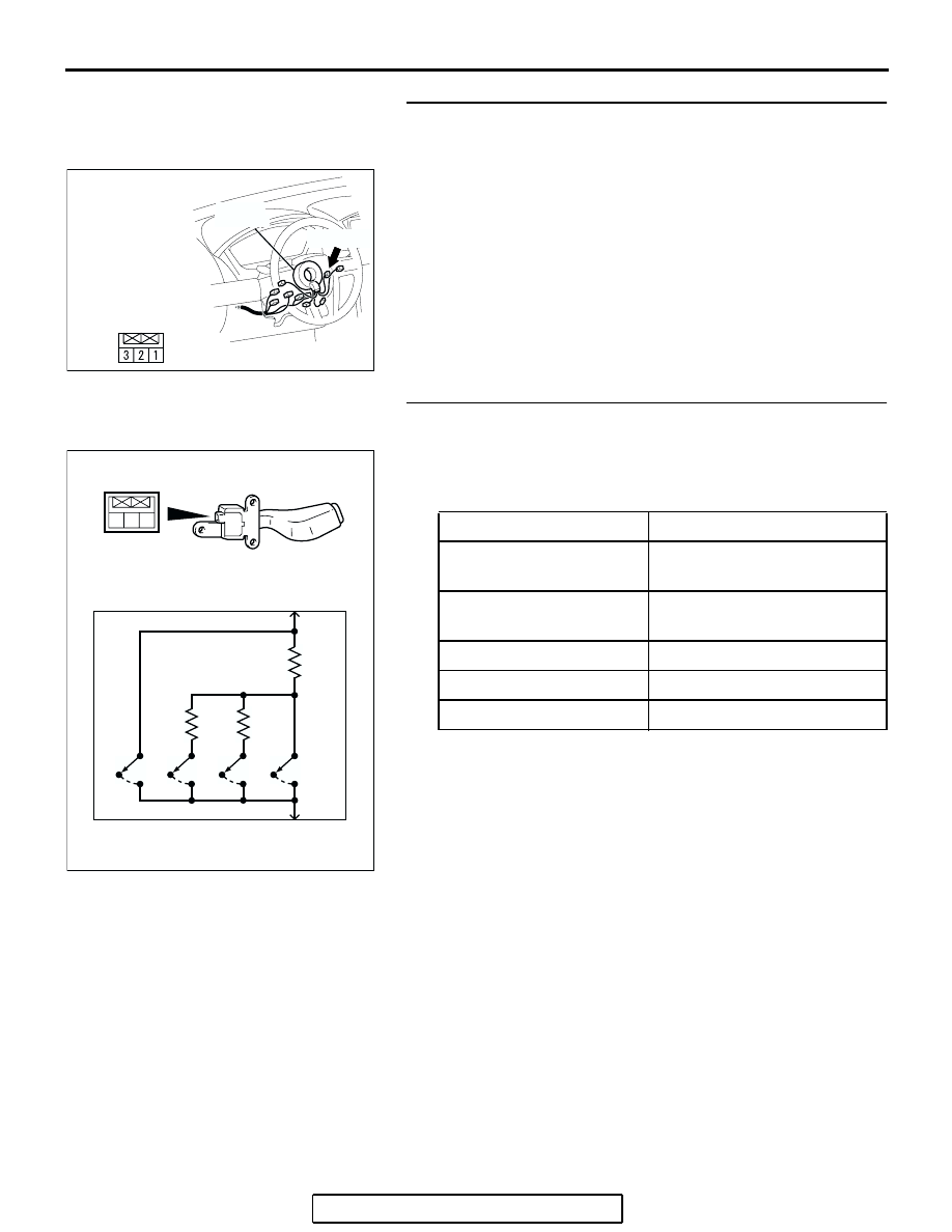
STEP 16. Check the auto-cruise control switch.
(1) Remove auto-cruise control switch. (Refer to 

P.17-74

).

(2) Measure the resistance between terminal 2 and terminal 3 

when each of the "CRUISE" (MAIN), "COAST/SET", 
"ACC/RES" and "CANCEL" switch is pressed.

Q: Is the resistance within specifications?

YES : Install the air bag module (driver’s side). (Refer to 

GROUP 52B, Air Bag Modules and Clock Spring 

P.52B-369

). Then go to Step 17.

NO :  Replace the auto-cruise control switch. (Refer to 

P.17-74

). Install the air bag module (driver’s side). 

(Refer to GROUP 52B, Air Bag Modules and Clock 
Spring 

P.52B-369

). Then go to Step 18.

AC305235AB

C-302 (Y)

CONNECTOR: C-302

C-302 HARNESS

CONNECTOR:

COMPONENT SIDE

CLOCK

SPRING

SWITCH POSITION

SPECIFIED CONDITION

"CRUISE" (MAIN) switch 
"OFF"

Open circuit

"CRUISE" (MAIN) switch 
"ON"

Less than 2 ohms

"CANCEL" switch ON

Approximately 100 

"ACC/RES" switch ON

Approximately 887 

"COAST/SET" switch ON Approximately 300 

1 2 3

AC203822AB

OFF

OFF

OFF

OFF

ON

ON

ON

ON

CAN

MAIN

RES

SET

2

3

AUTO-CRUISE CONTROL

TSB Revision

ENGINE AND EMISSION CONTROL

17-31

STEP 17. Using scan tool MB991958, read the diagnostic 
trouble code.

CAUTION

To prevent damage to scan tool MB991958, always turn the 
ignition switch to the "LOCK" (OFF) position before con-
necting or disconnecting scan tool MB991958. 
(1) Connect scan tool MB991958 to the data link connector. 

(Refer to 

P.17-11

).

(2) Turn the ignition switch to the "ON" position.
(3) Set scan tool MB991958 to read the diagnostic trouble 

codes. (Refer to 

P.17-11

).

(4) Turn the ignition switch to the "LOCK" (OFF) position.
(5) Disconnect scan tool MB991958.
Q: Is DTC 15 set?

YES : Replace the PCM. [Refer to GROUP 13A, Power 

Control Module (PCM) 

P.13A-1140

] <2.4L engine> or 

[Refer to GROUP 13B, Power Control Module (PCM) 

P.13B-1192

] <3.8L engine>. Then go to Step 18.

NO :  It can be assumed that this malfunction is intermittent. 

(Refer to GROUP 00, How to Use 
Troubleshooting/Inspection Service Points 

− How to 

Cope with Intermittent Malfunction 

P.00-14

).

STEP 18. Using scan tool MB991958, read the diagnostic 
trouble code.

CAUTION

To prevent damage to scan tool MB991958, always turn the 
ignition switch to the "LOCK" (OFF) position before con-
necting or disconnecting scan tool MB991958. 
(1) Connect scan tool MB991958 to the data link connector. 

(Refer to 

P.17-11

).

(2) Turn the ignition switch to the "ON" position.
(3) Set scan tool MB991958 to read the diagnostic trouble 

codes. (Refer to 

P.17-11

).

(4) Turn the ignition switch to the "LOCK" (OFF) position.
(5) Disconnect scan tool MB991958.
Q: Is DTC 15 set?

YES : Return to Step 1.
NO :  The procedure is complete.

AC305412

AB

MB991910

DATA LINK

CONNECTOR

MB991824

MB991827

AC305412

AB

MB991910

DATA LINK

CONNECTOR

MB991824

MB991827

AUTO-CRUISE CONTROL

TSB Revision

ENGINE AND EMISSION CONTROL

17-32

DTC 21: Cancel Latch Signal System

.

DTC SET CONDITIONS

The PCM communicates cancellation retention infor-
mation between the two microprocessors. This DTC 
is set when cancellation retention information con-
tains inconsistency.

.

TROUBLESHOOTING HINTS (THE MOST 
LIKELY CAUSES FOR THIS CODE TO BE 
SET ARE:)

Malfunction of the PCM.

DIAGNOSIS

Replace the PCM. [Refer to GROUP 13A, Power Control Mod-
ule (PCM) 

P.13A-1140

] <2.4L engine> or [Refer to GROUP 

13B, Power Control Module (PCM) 

P.13B-1192

] <3.8L 

engine>. Then check that diagnostic trouble code 21 is not set.

AUTO-CRUISE CONTROL

TSB Revision

ENGINE AND EMISSION CONTROL

17-33

DTC 22: Stoplight Switch System

AC305711

BATTERY

RELAY
BOX

WHITE

WHITE

GREEN-

BLACK

BLACK

BLACK

JOINT
CONNECTOR (1)

GREEN

STOPLIGHT

GREEN

LIGHT GREEN-

BLACK

POWERTRAIN CONTROL MODULE (PCM)

STOPLIGHT
SWITCH

GREEN

AB

Stoplight Switch System Circuit


Content   ..  451  452  453  454   ..