Mitsubishi Galant 9G. Manual - part 435


  Index      Mitsubishi     Mitsubishi Galant 9G - service repair manual


Search            


Content   ..  433  434  435  436   ..


Mitsubishi Galant 9G. Manual - part 435


TRACTION CONTROL SYSTEM (TCL) DIAGNOSIS

TSB Revision

TRACTION CONTROL SYSTEM (TCL)

13D-8

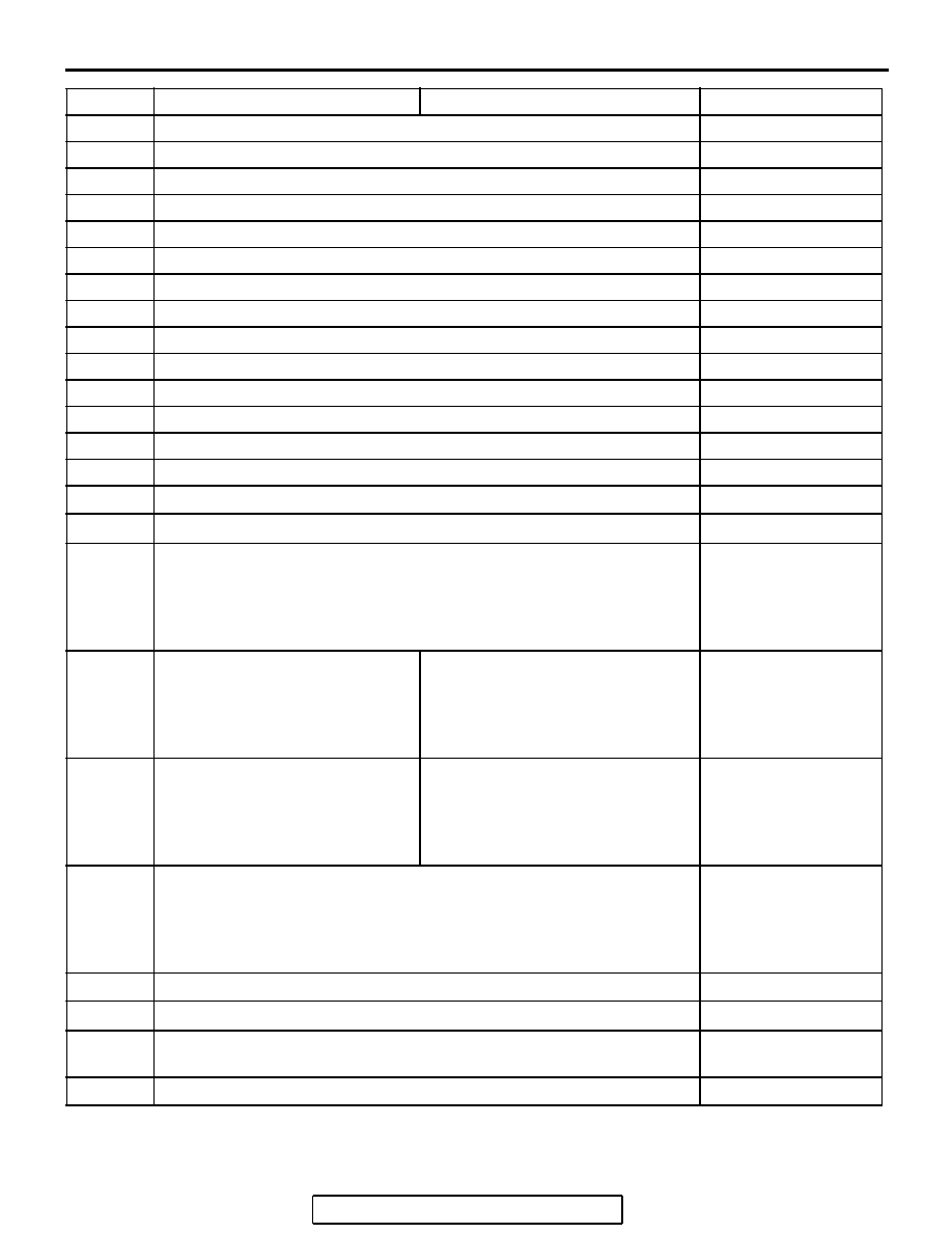
NOTE: Since the TCL is controlled with the same ABS/TCL-ECU used to control the ABS, the codes (with a 
*) used only for the ABS also appear.
The inspection contents for the codes (with a *) used only for the ABS do not described in this group.

C1226*

ABS front right solenoid inlet valve

-

C1231*

ABS front right solenoid outlet valve

-

C1236*

ABS front left solenoid valve inlet valve

-

C1241*

ABS front left solenoid valve outlet valve

-

C1246*

ABS rear right solenoid valve inlet valve

-

C1251*

ABS rear right solenoid valve outlet valve

-

C1256*

ABS rear left solenoid valve inlet valve

-

C1261*

ABS rear left solenoid valve outlet valve

-

C1266*

ABS hydraulic unit motor stuck

-

C1273*

ABS hydraulic unit motor drive circuit stuck off

-

C1274*

ABS hydraulic unit motor drive circuit stuck on

-

C1278*

ABS solenoid valve power circuit stuck off

-

C1279*

ABS solenoid valve power circuit stuck on

-

C1395*

Brake fluid filling incompleted

-

C1396

Engine torque intervention refusal

P.13D-9

C1397

Transmission range switch failure

P.13D-11

C1607

ABS/TCL-ECU failure

GROUP 35B, ABS 
Diagnosis 

− 

Diagnostic Trouble 
Code Procedures 
C1607 

P.35B-71

C1860

ABS/TCL-ECU power supply

Abnormal rise in voltage

GROUP 35B, ABS 
Diagnosis 

− 

Diagnostic Trouble 
Code Procedures 
C1860 

P.35B-73

C1861

ABS/TCL-ECU power supply

Abnormal drop in voltage

GROUP 35B, ABS 
Diagnosis 

− 

Diagnostic Trouble 
Code Procedures 
C1861 

P.35B-73

U1073

CAN communications system bus off

GROUP 35B, ABS 
Diagnosis 

− 

Diagnostic Trouble 
Code Procedures 
U1073 

P.35B-79

U1100

CAN communications system time out error engine related data

P.13D-13

U1101

CAN communications system time out error A/T related data

P.13D-17

U1120

CAN communications system TCL uncontrollable by engine 
malfunction

P.13D-21

U1400

Dynamic range error APS1

P.13D-25

DTC

INSPECTION ITEM

DIAGNOSTIC CONTENT

REFERENCE PAGE

TRACTION CONTROL SYSTEM (TCL) DIAGNOSIS

TSB Revision

TRACTION CONTROL SYSTEM (TCL)

13D-9

DIAGNOSTIC TROUBLE CODE PROCEDURES

C1396 Engine Torque Intervention Refusal

CAUTION

• If DTC C1396 is set in the ABS/TCL-ECU, 

always diagnose the CAN main bus line. If 
there is any fault in the CAN bus lines, an 
incorrect DTC may be set.

• Whenever the ABS/TCL-ECU is replaced, 

ensure that the communication circuit is nor-
mal.

.

DTC SET CONDITIONS

This DTC is set when the refusal of torque interven-
tion request is sent from PCM.

.

TROUBLESHOOTING HINTS (THE MOST 
LIKELY CAUSES FOR THIS CODE TO BE 
SET ARE:)

• Malfunction of the MFI system.

• Malfunction of the CAN bus line.

• Malfunction of the ABS/TCL-ECU.

DIAGNOSIS

Required Special Tools:

• MB991958: Scan Tool (MUT-III Sub Assembly)

• MB991824: V.C.I.

• MB991827: MUT-III USB Cable

• MB991910: MUT-III Main Harness A

STEP 1. Using scan tool MB991958, read the diagnostic 
trouble code.

CAUTION

To prevent damage to scan tool MB991958, always turn the 
ignition switch to the "LOCK" (OFF) position before con-
necting or disconnecting scan tool MB991958.
(1) Connect scan tool MB991958 to the data link connector. 

(Refer to 

P.13D-3

).

(2) Turn the ignition switch to the "ON" position.
(3) Check for MFI system diagnostic trouble code. (Refer to 

GROUP 13B, MFI Diagnosis 

− Diagnostic Function − How 

to Read and Erase Diagnostic Trouble Code 

P.13B-6

).

(4) Turn the ignition switch to the "LOCK" (OFF) position.
(5) Disconnect scan tool MB991958.
Q: Is any DTC set?

YES : Repair the MFI control system. (Refer to GROUP 

13B, MFI Diagnosis 

− Diagnostic Trouble Code Chart 

P.13B-34

). Then go to Step 4.

NO :  Go to Step 2.

AC305412

AB

MB991910

DATA LINK

CONNECTOR

MB991824

MB991827

TRACTION CONTROL SYSTEM (TCL) DIAGNOSIS

TSB Revision

TRACTION CONTROL SYSTEM (TCL)

13D-10

STEP 2. Using scan tool MB991958, diagnose the CAN bus 
line.

CAUTION

To prevent damage to scan tool MB991958, always turn the 
ignition switch to the "LOCK" (OFF) position before con-
necting or disconnecting scan tool MB991958.
(1) Connect scan tool MB991958 to the data link connector. 

(Refer to 

P.13D-3

).

(2) Turn the ignition switch to the "ON" position.
(3) Diagnose the CAN bus line. (Refer to 

P.13D-3

).

(4) Turn the ignition switch to the "LOCK" (OFF) position.
(5) Disconnect scan tool MB991958.
Q: Is any DTC set?

YES : Repair the CAN bus line. (Refer to GROUP 54C, 

Diagnosis 

− Can Bus Diagnostic Chart 

P.54C-14

). 

Then go to Step 4.

NO :  Go to Step 3.

STEP 3. Using scan tool MB991958, read the diagnostic 
trouble code.

CAUTION

To prevent damage to scan tool MB991958, always turn the 
ignition switch to the "LOCK" (OFF) position before con-
necting or disconnecting scan tool MB991958.
(1) Connect scan tool MB991958 to the data link connector. 

(Refer to 

P.13D-3

).

(2) Turn the ignition switch to the "ON" position.
(3) Use scan tool MB991958 to read the TCL diagnostic trouble 

codes. (Refer to 

P.13D-3

).

(4) Turn the ignition switch to the "LOCK" (OFF) position.
(5) Disconnect scan tool MB991958.
Q: Is DTC C1396 set?

YES : Replace the hydraulic unit (integrated with 

ABS/TCL-ECU). (Refer to GROUP 35B 

− Hydraulic 

Unit 

P.35B-105

). Then go to Step 4.

NO :  It can be assumed that this malfunction is intermittent. 

(Refer to GROUP 00, How to Use 
Troubleshooting/Inspection Service Points 

− How to 

Cope with Intermittent Malfunction 

P.00-14

).

AC305412

AB

MB991910

DATA LINK

CONNECTOR

MB991824

MB991827

AC305412

AB

MB991910

DATA LINK

CONNECTOR

MB991824

MB991827

TRACTION CONTROL SYSTEM (TCL) DIAGNOSIS

TSB Revision

TRACTION CONTROL SYSTEM (TCL)

13D-11

STEP 4. Using scan tool MB991958, read the diagnostic 
trouble code.

CAUTION

To prevent damage to scan tool MB991958, always turn the 
ignition switch to the "LOCK" (OFF) position before con-
necting or disconnecting scan tool MB991958.
(1) Connect scan tool MB991958 to the data link connector. 

(Refer to 

P.13D-3

).

(2) Turn the ignition switch to the "ON" position.
(3) Use scan tool MB991958 to read the TCL diagnostic trouble 

codes. (Refer to 

P.13D-3

).

(4) Turn the ignition switch to the "LOCK" (OFF) position.
(5) Disconnect scan tool MB991958.
Q: Is DTC C1396 set?

YES : Return to Step 1.
NO :  The procedure is complete.

C1397 Transmission Range Switch Failure

CAUTION

• If DTC C1397 is set in the ABS/TCL-ECU, 

always diagnose the CAN main bus line. If 
there is any fault in the CAN bus lines, an 
incorrect DTC may be set.

• Whenever the ABS/TCL-ECU is replaced, 

ensure that the communication circuit is nor-
mal.

• The A/T system-related DTC may be set when 

DTC C1397 is set. (For details refer to GROUP 
00, Intersystem Affiliated DTC Reference 
Table 

P.00-17

). Diagnose the A/T system first 

when the A/T system-related DTC is set.

.

DTC SET CONDITIONS

This DTC is set when the transmission range switch 
fail request is sent from PCM.

.

TROUBLESHOOTING HINTS (THE MOST 
LIKELY CAUSES FOR THIS CODE TO BE 
SET ARE:)

• Malfunction of the A/T system.

• Malfunction of the ABS/TCL-ECU.

DIAGNOSIS

Required Special Tools:

• MB991958: Scan Tool (MUT-III Sub Assembly)

• MB991824: V.C.I.

• MB991827: MUT-III USB Cable

• MB991910: MUT-III Main Harness A

AC305412

AB

MB991910

DATA LINK

CONNECTOR

MB991824

MB991827


Content   ..  433  434  435  436   ..