Mitsubishi Galant 9G. Manual - part 434
TRACTION CONTROL SYSTEM (TCL) DIAGNOSIS
TSB Revision
TRACTION CONTROL SYSTEM (TCL)
13D-4
HOW TO READ AND ERASE DIAGNOSTIC
TROUBLE CODES
Required Special Tools:
• MB991958: Scan Tool (MUT-III Sub Assembly)
• MB991824: V.C.I.
• MB991827: MUT-III USB Cable
• MB991910: MUT-III Main Harness A
CAUTION
To prevent damage to scan tool MB991958, always turn the
ignition switch to the "LOCK" (OFF) position before con-
necting or disconnecting scan tool MB991958.
NOTE: If the battery voltage is low, diagnostic trouble codes
will not be set. Check the battery if scan tool MB991958
does not display.
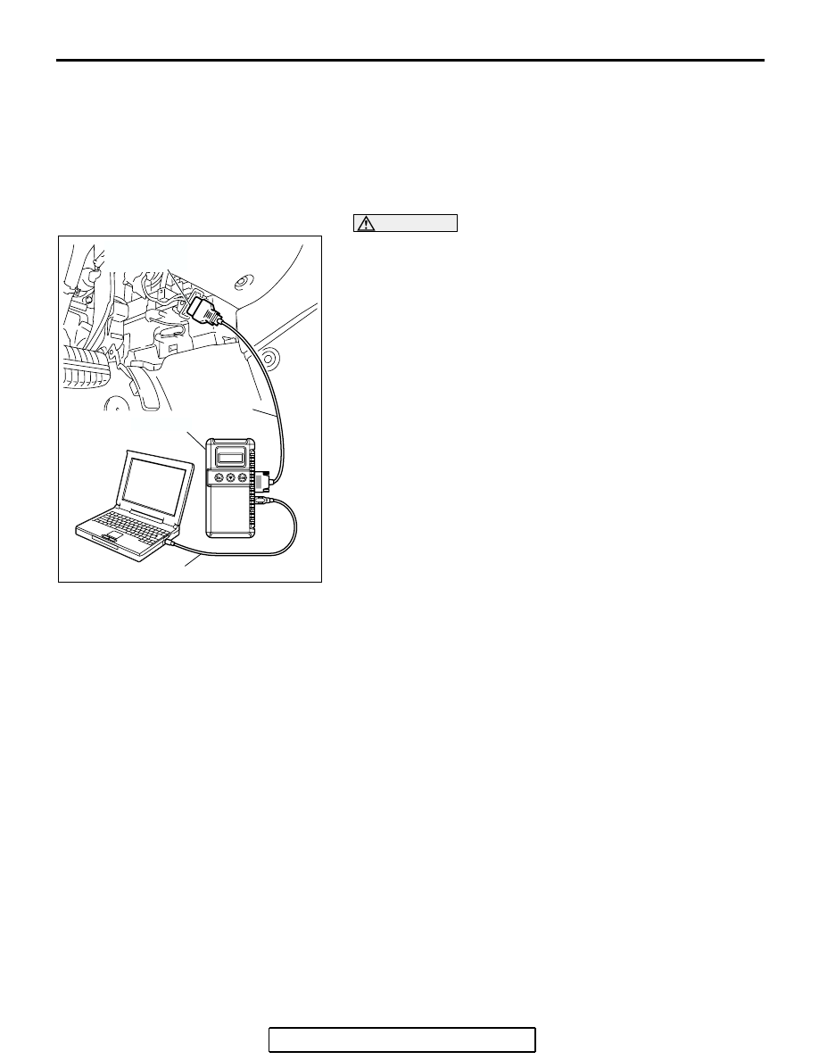
1. Connect scan tool MB991958 to the data link connector.
2. Turn the ignition switch to the "ON" position.
3. Select "Interactive Diagnosis" from the start-up screen.
4. Select "System Select".
5. Choose "TCL" from the "POWERTRAIN" tab.
6. Select "Diagnostic Trouble Code".
7. If a DTC is set, it is shown.
8. Choose "DTC erase" to erase the DTC.
9. Turn the ignition switch to the "LOCK" (OFF) position.
10.Disconnect scan tool MB991958.
HOW TO READ DATA LIST
Required Special Tools:
• MB991958: Scan Tool (MUT-III Sub Assembly)
• MB991824: V.C.I.
• MB991827: MUT-III USB Cable
• MB991910: MUT-III Main Harness A
AC305412
AB
MB991910
DATA LINK
CONNECTOR
MB991824
MB991827