Mitsubishi Galant 9G. Manual - part 431
MAINTENANCE SERVICE
TSB Revision
GENERAL
00-62
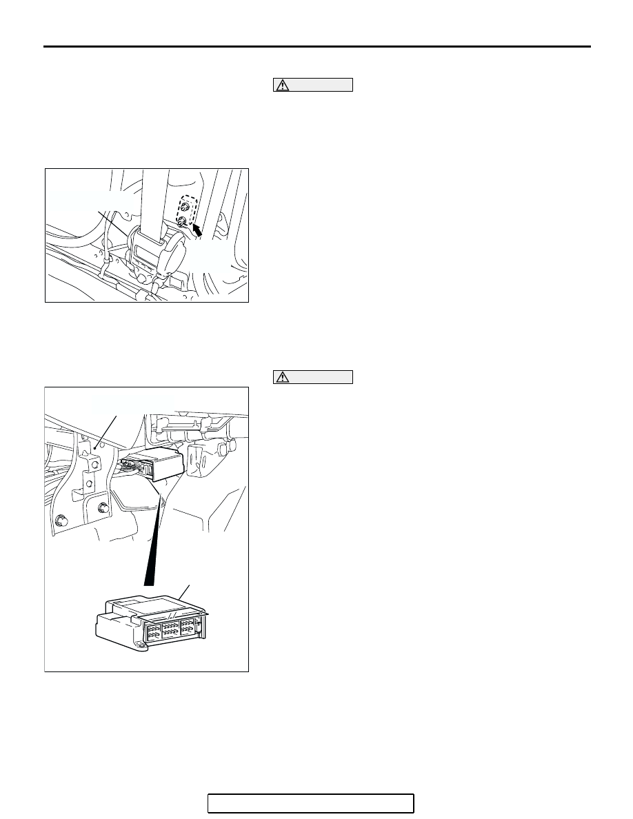
SIDE IMPACT SENSORS
WARNING
•
If the side impact sensor is not installed securely
and correctly, the side-air bag may not operate
normally.
•
If a dent, crack, deformation or rust is detected,
replace with a new sensor.
1. Check the side impact sensor and bracket for dents, cracks
or deformation. The side impact sensors are located inside
the center pillars (LH/RH).
2. Check the connector for damage, and terminal for
deformation.
3. Check that there is no bending or corrosion in the center
pillars (LH/RH).
Replace the side impact sensor if it fails the visual check
(Refer to GROUP 52B, Side Impact Sensor
NOTE: The illustration shows the left side impact sensor (RH).
The position of the other side impact sensor (LH) is symmetri-
cal to this.
SRS AIR BAG CONTROL UNIT (SRS-ECU)
WARNING
The SRS may not activate if the SRS-ECU is not
installed properly, which could result in serious injury
or death to the vehicle's driver and front passenger.
1. Check the SRS-ECU case for dents, cracks, deformation or
rust.
2. Check the connector for damage, and check the terminals
for deformation or rust.
Replace the SRS-ECU if it fails the visual checks above
(Refer to GROUP 52B, SRS Air Bag Control Unit
).
AC206185 AC
FRONT SEAT BELT
RETRACTOR
SIDE
IMPACT
SENSOR
AC308239
SRS-ECU
AB
CENTER
REINFORCEMENT