Mitsubishi Galant 9G. Manual - part 421
VEHICLE IDENTIFICATION
TSB Revision
GENERAL
00-22
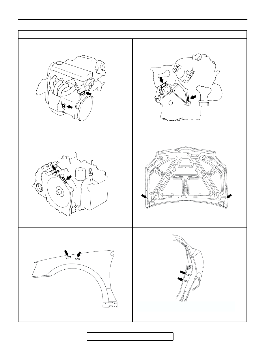
LOCATIONS
LABEL AREA (A: FOR ORIGINAL EQUIPMENT PARTS, B: FOR REPLACEMENT PARTS)
AC000058
ENGINE
<2.4L ENGINE>
AD
A
B
AC000061
ENGINE
<3.8L ENGINE>
AC
B
A
AC000060
AUTOMATIC TRANSAXLE
AB
A
B
AC307026AB
A
B
HOOD
AC307027
A
B
FENDER
THE ILLUSTRATION INDICATES
LEFT OUTER SIDE.
RIGHT SIDE IS SYMMETRICALLY
OPPOSITE.
AB
AC307028AB
A
B
REAR QUARTER OUTER PANEL
THE ILLUSTRATION INDICATES LEFT OUTER SIDE.
RIGHT SIDE IS SYMMETRICALLY OPPOSITE.