Mitsubishi Galant 9G. Manual - part 396


  Index      Mitsubishi     Mitsubishi Galant 9G - service repair manual


Search            


Content   ..  394  395  396  397   ..


Mitsubishi Galant 9G. Manual - part 396


TRUNK LID

TSB Revision

BODY

42-64

REMOVAL SERVICE POINT

.

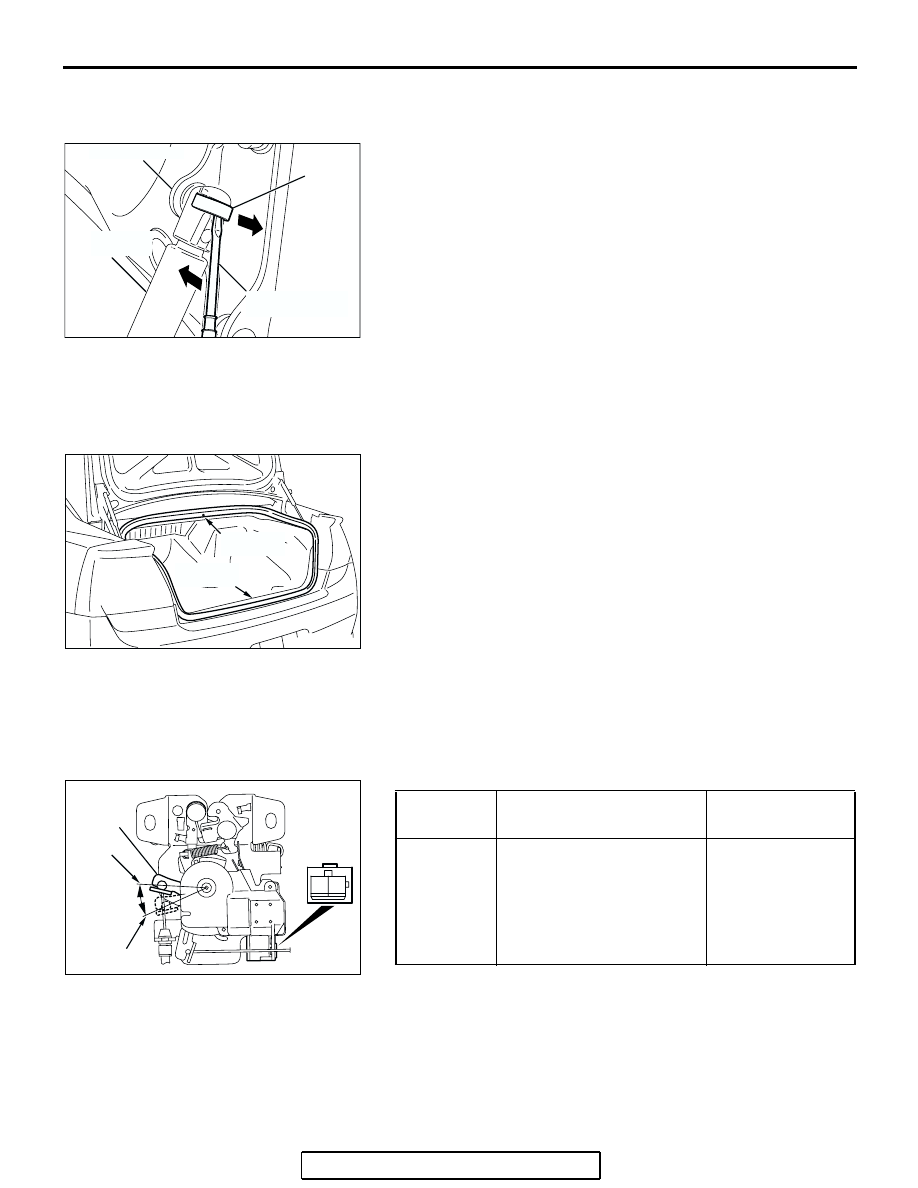
<<A>> TRUNK LID GAS SPRING REMOVAL

As shown in the figure, slide the pin upward, then remove the 
trunk lid gas spring in the direction of the arrow to unscrew the 
trunk lid hinge.

INSTALLATION SERVICE POINT

.

>>A<< TRUNK LID WEATHERSTRIP 
INSTALLATION

Install the trunk lid weatherstrip so that the marking and the 
joint are aligned with the body center line,

INSPECTION

M1421004800144

TRUNK LID LATCH ASSEMBLY CHECK

.

TRUNK LID LATCH ACTUATOR CHECK

.

AC305996

PIN

AB

TRUNK LID 
GAS SPRING

TRUNK LID HINGE

FLAT-TAPPED 
SCREWDRIVER

AC305825 AB

MARKING

SECTION

JOINT

SECTION

LEVER 
POSITION

BATTERY CONNECTION LEVER 

OPERATION

At the "OFF" 
position

• Connect ground and the 

negative battery 
terminal.

• Connect terminal No. 1 

and the positive battery 
terminal.

The lever moves 
from the "OFF" 
position to the 
"OPEN" position.

AC305826

1

2

AB

OFF

LEVER

OPEN

<REAR VIEW>

KEYLESS ENTRY SYSTEM

TSB Revision

BODY

42-65

TRUNK LID LATCH SWITCH CONTINUITY CHECK

KEYLESS ENTRY SYSTEM

GENERAL DESCRIPTION

M1428000100229

• Antenna and receiver are incorporated in the 

ETACS-ECU.

• ID code can be registered by using scan tool 

MB991958 (MUT-III sub assembly).

• Transmitter is a key holder type, which incorpo-

rates lock button, unlock button, trunk button and 
panic button <Vehicles with panic alarm system>.

• When the transmitter unlock button is pressed 

once, the driver's door will be unlocked. If the but-
ton is pressed twice, all the doors will be 
unlocked. The adjustment function also allows 
you to open all the doors by pressing the unlock 
button only once. For further details on using the 
multi-center display (middle grade type) to adjust 
the unlock operation, refer to GROUP 54B, 
On-vehicle Servic

P.54B-555

.

• When the transmitter is operated, the answer-

back function will work as follows:

• The answerback operation can be altered as fol-

lows:

NOTE: Enabling/disabling the hazard warning 
light flashing, the horn sounding in accordance 
with the answerback function. For further details 
on using the transmitter to adjust answerback, 

P.42-69

 see the section below. For further details 

on using the multi-center display (middle grade 
type) to adjust answerback, refer to GROUP 54B, 
On-vehicle Servic

P.54B-555

.

LEVER POSITION TESTER 

CONNECTION

SPECIFIED 
CONDITION

ON (Latch open)

− Ground 

Less than 2 ohms

OFF (Latch shut)

− Ground 

Open circuit

AC305827

1

2

AB

<FRONT 
VIEW>

ON

OFF

LEVER

ITEM

OPERATION
DOORS LOCKED

DOORS UNLOCKED

Dome light

Flashes once

Illuminates for 15 seconds

Turn-signal lights (RH and LH)

Flashes once

Flashes twice

Horn

Sounds once when the lock button 
is pressed with all the doors locked

-

KEYLESS ENTRY SYSTEM

TSB Revision

BODY

42-66

• If none of the doors is opened or the ignition key 

is not inserted in the ignition switch within 30 sec-
onds after the doors are unlocked using the 
transmitter, the ETACS-ECU will relock the doors 
automatically. This is called "Timer lock function." 
This timer lock function prevents accidental 
unlocking of doors. The adjustment function 
allows you to change the timer lock period from 

30 seconds (default setting) to 60, 120 or 180 
seconds. For further details on using the 
multi-center display (middle grade type) to adjust 
the timer lock period, refer to GROUP 54B, 
On-vehicle Servic

P.54B-555

.

NOTE: The timer lock period begins when the doors 
are unlocked, and ends when the doors is relocked 
automatically.

KEYLESS ENTRY SYSTEM DIAGNOSIS

M1428000700298

The keyless entry system is controlled by the Simpli-
fied Wiring System (SWS). Refer to GROUP 54B, 
SWS Diagnosis 

P.54B-59

.

ITEM

ADJUSTMENT ITEM

ADJUSTMENT DETAIL

Keyless entry system 
confirmation by turn 
signal lights

Adjustment of hazard answerback 
when the transmitter is used to 
lock doors

When adjusting hazard answerback after the 
doors are locked with the transmitter, the 
following flashing conditions can be selected.

a. Flash (default)
b. No flash

Adjustment of hazard answerback 
when the transmitter is used to 
unlock doors

When adjusting hazard answerback after the 
doors are unlocked with the transmitter, the 
following flashing conditions can be selected.

a. Flash (default)
b. No flash

Keyless entry system 
confirmation by horn

Adjustment of horn answerback 
when the transmitter is used to 
lock doors

When adjusting horn answerback after the 
doors are locked with the transmitter, the 
following horn conditions can be selected.

a. Horn sounds
b. Horn sounds if doors are already locked 

(default)

c. Horn does not sound

KEYLESS ENTRY SYSTEM

TSB Revision

BODY

42-67

SPECIAL TOOL

M1428000600291

TOOL

TOOL NUMBER AND 
NAME

SUPERSESSION

APPLICATION

MB991958

A: MB991824
B: MB991827
C: MB991910
D: MB991911
E: MB991914
F: MB991825
G: MB991826

MUT-III Sub Assembly

A: Vehicle communication 

interface (V.C.I.)

B: MUT-III USB cable
C: MUT-III main harness A 

(Vehicles with CAN 
communication system)

D: MUT-III main harness B 

(Vehicles without CAN 
communication system)

E: MUT-III main harness C 

(for Daimler Chrysler 
models only)

F: MUT-III measurement 

adapter

G: MUT-III trigger harness

MB991824-KIT
NOTE: G: MB991826 
MUT-III Trigger Harness is 
not necessary when 
pushing V.C.I. ENTER key.

For registration of secret 
code

CAUTION

For vehicles with CAN 
communication, use 
MUT-III main harness A to 
send simulated vehicle 
speed. If you connect 
MUT-III main harness B 
instead, the CAN 
communication does not 
function correctly.

MB991910

MB991826

MB991958

MB991911

MB991914

MB991824

MB991827

MB991825

DO NOT USE

A

B

C

D

E

F

G

DO NOT USE


Content   ..  394  395  396  397   ..