Mitsubishi Galant 9G. Manual - part 364


  Index      Mitsubishi     Mitsubishi Galant 9G - service repair manual


Search            


Content   ..  362  363  364  365   ..


Mitsubishi Galant 9G. Manual - part 364


GENERAL DESCRIPTION

TSB Revision

POWER PLANT MOUNT

32-2

GENERAL DESCRIPTION

M1321000100373

• The engine front mounting bracket is a 

dome-shaped fluid-filled mount for improved 
responsiveness during acceleration and more 
stable vehicle performance against road distur-
bances.

• The liquid-filled transaxle mounting body side 

bracket improves riding comfort by its refined 
insulator.

• A roll stopper bracket in the upper area limits 

engine rolling. Furthermore, large diameter insu-
lator reduces idle vibration.

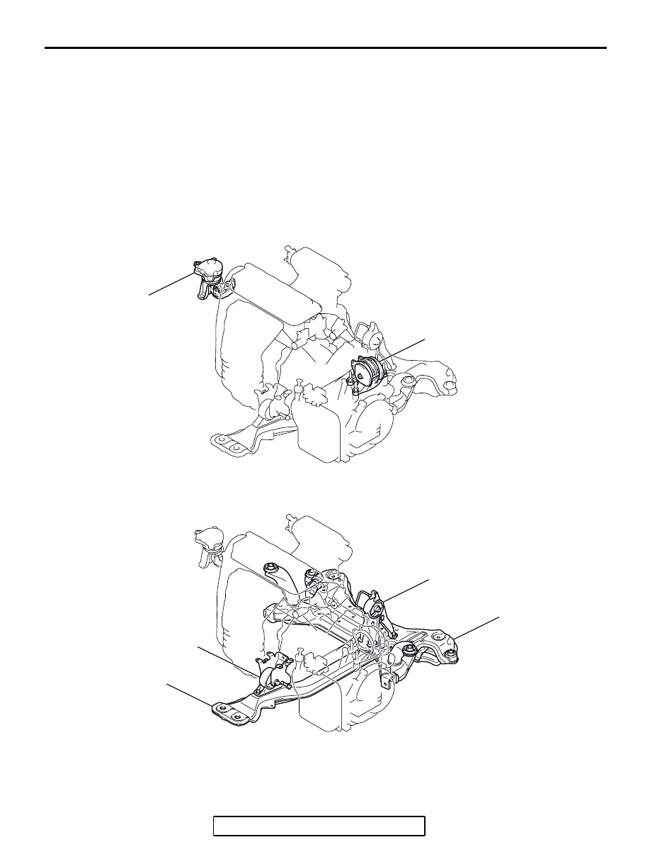
CONSTRUCTION DIAGRAM
<2.4L ENGINE>

AC305858

AC305857

AC305859

ENGINE FRONT 
MOUNTING
BRACKET

TRANSAXLE MOUNTING
BODY SIDE BRACKET

ENGINE REAR 
ROLL STOPPER 
BRACKET

FRONT AXLE NO.1 
CROSSMEMBER

ENGINE FRONT 
ROLL STOPPER 
BRACKET

CENTERMEMBER

AB

SPECIAL TOOL

TSB Revision

POWER PLANT MOUNT

32-3

<3.8L ENGINE>

SPECIAL TOOL

M1321000600390

AC305861

AC305860

AC305862

ENGINE FRONT 
MOUNTING
BRACKET

TRANSAXLE MOUNTING
BODY SIDE BRACKET

ENGINE REAR 
ROLL STOPPER 
BRACKET

FRONT AXLE NO.1 
CROSSMEMBER

ENGINE FRONT 
ROLL STOPPER 
BRACKET

CENTERMEMBER

AB

TOOL

TOOL NUMBER 
AND NAME

SUPERSESSION

APPLICATION

MB991897
Ball joint remover

MB991113-01, 
MB990635-01 or 
General service tool 

Knuckle and tie rod end ball joint 
disconnection
NOTE: Steering linkage  puller 
(MB990635 or MB991113)is also 
used to disconnect the knuckle 
and tie rod end ball joint.

AC106827

ENGINE MOUNTING

TSB Revision

POWER PLANT MOUNT

32-4

ENGINE MOUNTING

REMOVAL AND INSTALLATION

M1321001100462

CAUTION

*: Indicates parts which should be initially tightened, and then fully tightened after placing the vehicle 
horizontally and loading the full weight of the engine on the vehicle body.

REMOVAL SERVICE POINT

.

<<A>>  POWER STEERING OIL  RESERVOIR 
REMOVAL

With the hose installed, remove the power steering oil reservoir 
from the vehicle. (Refer to GROUP 37, Power Steering Hoses 

P.37-58

).

NOTE: After removing the power steering oil reservoir, secure it 
with a cord in the location where the removal and installation of 
the engine front mounting bracket cannot be hindered. 

Pre-removal Operation
Raise the engine and transaxle assembly until its weight is 
not applied to the insulator, and support it securely.

AC307311

4

2

3

83 ± 12 N·m*
61 ± 9 ft-lb* 

58 ± 7 N·m*
43 ± 5 ft-lb* 

N

58 ± 7 N·m*
43 ± 5 ft-lb* 

4

2

3

83 ± 12 N·m*
61 ± 9 ft-lb* 

58 ± 7 N·m*
43 ± 5 ft-lb* 

N

58 ± 7 N·m*
43 ± 5 ft-lb* 

1

36 ± 6 N·m
27 ± 4 ft-lb

83 ± 12 N·m*
61 ± 9 ft-lb* 

AB

<2.4L ENGINE>

<3.8L ENGINE>

9.0 ± 2.0 N·m
80 ± 17 in-lb

9.0 ± 2.0 N·m
80 ± 17 in-lb

REMOVAL STEPS

1.

ENGINE MOUNTING STAY <3.8L 
ENGINE>

2.

GROUNDING CABLE 
CONNECTION

<<A>>

POWER STEERING OIL 
RESERVOIR

3.

SELF-LOCKING NUTS

4.

ENGINE FRONT MOUNTING 
BRACKET

REMOVAL STEPS (Continued)

TRANSAXLE MOUNTING

TSB Revision

POWER PLANT MOUNT

32-5

TRANSAXLE MOUNTING

REMOVAL AND INSTALLATION

M1321001400452

CAUTION

*: Indicates parts which should be initially tightened, and then fully tightened after placing the vehicle 
horizontally and loading the full weight of the engine on the vehicle body.

Pre-removal Operation
• Powertrain Control Module (PCM) Removal (2.4L 

ENGINE: Refer to GROUP 13A, Powertrain Control Mod-

ule (PCM) 

P.13A-1140

, 3.8L ENGINE:  Refer to GROUP 

13B, Powertrain Control Module (PCM

P.13B-1192

).

• Air Cleaner Removal (Refer to GROUP 15, Air Cleaner 

P.15-4

).

• Battery and Battery Tray Removal

• Centermember Removal (Refer to 

P.32-7

).

• Engine Rear Roll Stopper Bracket Removal (Refer to 

P.32-7

).

• Raise the engine and transaxle assembly until its weight 

is not applied to the insulator, and support it securely.

Post-installation Operation
• Engine Rear Roll Stopper Bracket Installation (Refer to 

P.32-7

).

• Centermember Installation (Refer to 

P.32-7

).

• Battery and Battery Tray Installation

• Air Cleaner Installation (Refer to GROUP 15, Air Cleaner 

P.15-4

).

• Powertrain Control Module (PCM) Installation (2.4L 

ENGINE: Refer to GROUP 13A, Powertrain Control Mod-

ule (PCM

P.13A-1140

, 3.8L ENGINE: Refer to GROUP 

13B, Powertrain Control Module (PCM

P.13B-1192

).

AC306763

1

2

3

83 ± 12 N·m*
61 ± 9 ft-lb*

58 ± 7 N·m*
43 ± 5  ft-lb*

AB

N

3

REMOVAL STEPS

1.

SELF-LOCKING NUTS

2.

TRANSAXLE MOUNTING BODY 
SIDE BRACKET

>>A<<

3.

TRANSAXLE MOUNTING 
STOPPER

REMOVAL STEPS (Continued)


Content   ..  362  363  364  365   ..