Mitsubishi Galant 9G. Manual - part 359


  Index      Mitsubishi     Mitsubishi Galant 9G - service repair manual


Search            


Content   ..  357  358  359  360   ..


Mitsubishi Galant 9G. Manual - part 359


STARTING SYSTEM

TSB Revision

ENGINE ELECTRICAL

16-32

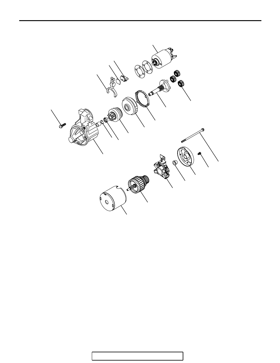
DISASSEMBLY AND ASSEMBLY

M1162001200150

AK204336AB

1

2

18

19

10

11

12

13

14

15 16

17

20

3

4

5

6

7

8

9

DISASSEMBLY STEPS

1. SCREW
2. MAGNETIC SWITCH
3. SCREW
4. SCREW
5. REAR BRACKET
6. BRUSH
7. REAR BEARING
8. ARMATURE
9. YOKE ASSEMBLY
10. PACKING A

11. PACKING B
12. PLATE
13. PLANETARY GEAR
14. LEVER

<<A>>>A<<

15. SNAP RING

<<A>>>A<<

16. STOP RING
17. OVERRUNNING CLUTCH
18. INTERNAL GEAR
19. PLANETARY GEAR HOLDER
20. FRONT BRACKET

DISASSEMBLY STEPS 

STARTING SYSTEM

TSB Revision

ENGINE ELECTRICAL

16-33

DISASSEMBLY SERVICE POINTS

.

<<A>>  SNAP RING AND STOP  RING  REMOVAL

1. Press a long socket wrench of appropriate size to the stop 

ring. Then tap the socket wrench to remove the stop ring to 
the pinion gear side.

2. After removing the snap ring (by using snap-ring pliers), 

remove the stop ring and the overrunning clutch.

STARTER MOTOR PART CLEANING

1. Do not immerse parts in cleaning solvent. Immersing the 

yoke and field coil assembly and/or armature will damage 
insulation. Wipe these parts with a shop towel only.

2. Do not immerse the drive unit in cleaning solvent. 

Overrunning clutch is pre-lubricated at the factory and 
solvent will wash lubrication from the clutch.

3. The drive unit may be cleaned with a brush moistened with 

cleaning solvent and wiped dry with a shop towel.

ASSEMBLY SERVICE POINT

.

>>A<< STOP RING AND SNAP RING INSTALLA-
TION

Using a suitable pulling tool, pull the overrunning clutch stop 
ring over the snap ring.

AKX00370

SOCKET

STOP RING

PINION GEAR

OVERRUNNING
CLUTCH

AB

AKX00371

SNAP RING

PINION GEAR

OVERRUNNING
CLUTCH

SNAP-RING
PLIERS

AB

AKX00372

STOP RING

OVERRUNNING
CLUTCH

SNAP RING

STOP 
RING

AB

STARTING SYSTEM

TSB Revision

ENGINE ELECTRICAL

16-34

INSPECTION

M1162001300102

.

COMMUTATOR CHECK

1. Place the armature on a pair of V-blocks, and check the 

deflection by using a dial gauge.

Standard value: 0.05 mm (0.002 inch)
Limit: 0.1 mm (0.004 inch)

2. Check the outer diameter of the commutator.

Standard value: 29.4 mm (1.16 inches)
Minimum limit: 28.8 mm (1.13 inches)

3. Check the depth of the undercut between segments.

Standard value: 0.5 mm (0.02 inch)
Minimum limit: 0.2 mm (0.008 inch)

.

BRUSH CHECK

1. Check the brush for roughness of the surface that contacts 

the commutator and check the brush length. Replace the 
brush holder if this measurement exceeds the limit.

Minimum limit:

 7.0 mm (0.28 inch)

2. If the contacting surface has been corrected or the brush 

has been replaced, correct the contacting surface by 
winding sandpaper around the commutator.

.

AKX00373

AKX00374

AKX00375

SEGMENT

UNDERCUT

MICA

AB

AK101390

LIMIT LENGTH

AB

STARTING SYSTEM

TSB Revision

ENGINE ELECTRICAL

16-35

OVERRUNNING CLUTCH CHECK

1. While holding the clutch housing, rotate the pinion. The drive 

pinion should rotate smoothly in one direction, but should 
not rotate in the opposite direction. If the clutch does not 
function properly, replace the overrunning clutch assembly.

2. Inspect the pinion for wear or burrs. If the pinion is worn or 

burred, replace the overrunning clutch assembly. If the 
pinion is damaged, also inspect the ring gear for wear or 
burrs.

.

FRONT AND REAR BRACKET BUSHING CHECK

Inspect the bushing for wear or burrs. If the bushing is worn or 
burred, replace the front bracket assembly or rear bracket 
assembly.

.

ARMATURE CHECK

1. Check that the armature coil is not grounded.
2. Place the armature in a growler.
3. Hold a thin steel blade parallel and just above while rotating 

the armature slowly in the growler. A shorted armature will 
cause a blade to vibrate and be attracted to the core. 
Replace the shorted armature.

4. Check the insulation between the armature coil cores and 

the commutator segments. They are normal if there is no 
continuity.

5. Check for continuity between the segments. The condition is 

normal if there is continuity.

AKX00378

FREE

LOCK

AB

AKX00379

GROWLER

AB

AKX00380

AKX00381


Content   ..  357  358  359  360   ..