Mitsubishi Galant 9G. Manual - part 357


  Index      Mitsubishi     Mitsubishi Galant 9G - service repair manual


Search            


Content   ..  355  356  357  358   ..


Mitsubishi Galant 9G. Manual - part 357


STARTING SYSTEM

TSB Revision

ENGINE ELECTRICAL

16-24

STARTING SYSTEM

GENERAL DESCRIPTION

M1162000100235

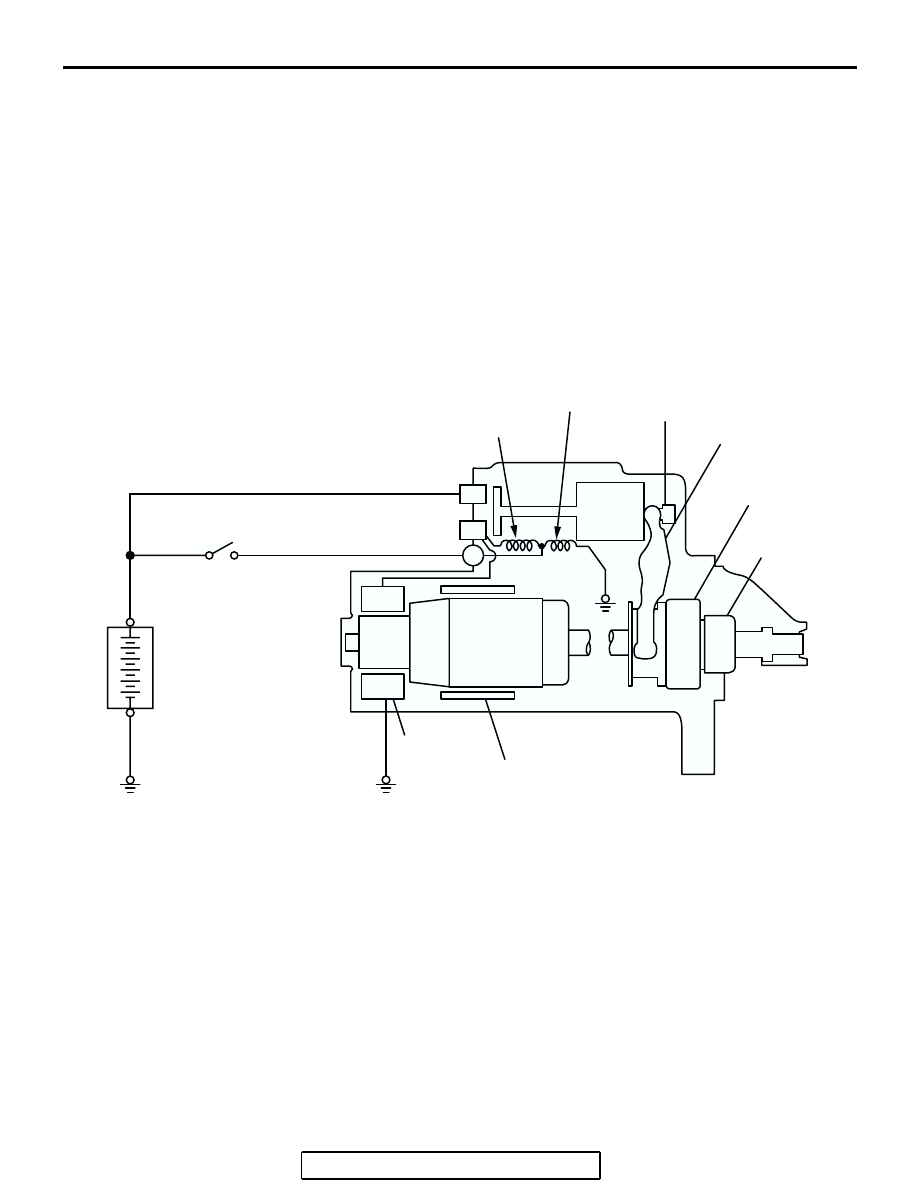
If the ignition switch is turned to the "START" posi-
tion, current flows in the coil provided inside mag-
netic switch, attracting the plunger. When the plunger 
is attracted, the lever connected to the plunger is 
actuated to engage the starter clutch.
On the other hand, attracting the plunger will turn on 
the magnetic switch, allowing the "B" terminal and 
"M" terminal to conduct. Thus, current flows to 
engage the starter motor.

When the ignition switch is returned to the "ON" posi-
tion after starting the engine, the starter clutch is dis-
engaged from the ring gear.
An overrunning clutch is provided between the pinion 
and the armature shaft, to prevent damage to the 
starter.

OPERATION

When the ignition switch is switched to the "ST" posi-
tion while the selector lever is at the "P" or "N" range, 
the contact (magnetic switch) of the starter is 
switched ON and the starter motor is activated.

AK202970

PULL-IN COIL

HOLDING
COIL

PLUNGER

LEVER

PINION GEAR

OVERRUNNING
CLUTCH

YOKE

BRUSH

ARMATURE

IGNITION
SWITCH

BATTERY

+

AC

B

M

S

STARTING SYSTEM

TSB Revision

ENGINE ELECTRICAL

16-25

STARTING SYSTEM DIAGNOSIS

M1162000700293

TROUBLESHOOTING HINTS

The starter motor does not operate at all.

WARNING

Battery posts, terminals and related accessories con-
tain lead and lead compounds. WASH HANDS AFTER 
HANDLING.

• Check the starter (coil).

• Check for poor contact at the battery terminals and 

starter.

• Check the transmission range switch.

The starter motor doesn't stop

• Check the starter (magnetic switch).

TROUBLESHOOTING GUIDE

The starting system troubleshooting guide is shown in the fol-
lowing steps.

WARNING

Battery posts, terminals and related accessories con-
tain lead and lead compounds. WASH HANDS AFTER 
HANDLING.

STEP 1.
Q: Is the battery in good condition? (Refer to GROUP 54A, 

Chassis Electrical 

 Battery  On-vehicle Service  

Battery Check 

P.54A-5

.)

YES : Go to Step 2.
NO :  Charge or replace the battery.

STEP 2.

• Disconnect the starter motor S (solenoid) terminal connec-

tor.

• Using a jumper wire, apply battery positive voltage to the 

starter motor S (solenoid) terminal.

• Check the engine condition.

OK: Turns normally

Q: Dose the starter motor operate normally?

YES : 

• Check the ignition switch (Refer to GROUP 54A, 

Chassis Electrical 

− Ignition Switch − Ignition 

Switch 

− Inspection 

P.54A-48

.)

• Check the transmission range switch. (Refer to 

GROUP 23A, Automatic Transaxle 

− On-vehicle 

Service 

− Essential Service − Transmission Range 

Switch Check 

P.23A-372

.)

• Check the line between the battery and starter 

motor S (solenoid) terminal.

NO :  Go to Step 3.

STARTING SYSTEM

TSB Revision

ENGINE ELECTRICAL

16-26

STEP 3.

• Check the cable between starter B (battery) terminal and 

battery positive terminal for connection and continuity.

Q: Is the starter cable in good condition?

YES : Go to Step 4.
NO :  Repair or replace the cable.

STEP 4.

• Check the connection and the continuity of the cable 

between the starter motor body and the negative battery 
terminal.

Q: Is the ground line in good condition?

YES : Go to Step 5.
NO :  Repair or replace the cable.

STEP 5.
Q: Is the starter motor in good condition? (Refer to Starting 

System 

 Starter Motor Assembly  Inspection 

P.16-21

.)

YES : Excessive rotational resistance of the engine.
NO :  Replace the starter motor.

STARTER MOTOR ASSEMBLY

REMOVAL AND INSTALLATION <2.4L ENGINE>

M1162001000662

Pre-removal and Post-installation Operation
Air Cleaner Removal and Installation (Refer to GROUP 15, 
Air Cleaner 

P.15-4

).

AC306713AB

1

5

4

3

2

23 ± 3 N·m
17 ± 2 ft-lb

12 ± 2 N·m
102 ± 22 in-lb

9.0 ± 2.0 N·m
80 ± 17 in-lb

30 ± 3 N·m
23 ± 2 ft-lb

49 ± 9 N·m
36 ± 7 ft-lb

9.0 ± 2.0 N·m
80 ± 17 in-lb

STARTING SYSTEM

TSB Revision

ENGINE ELECTRICAL

16-27

REMOVAL SERVICE POINTS

.

<<A>> ATF WARMER (TRANSMISSION FLUID 
COOLER) AND BRACKET ASSEMBLY REMOVAL

With the hose installed, remove the ATF warmer (transmission 
fluid cooler) &bracket assembly from the transmission case 
front roll stopper bracket.

.

<<B>> STARTER ASSEMBLY REMOVAL

Remove the starter assembly  from the side of ATF warmer 
(transmission fluid cooler).

REMOVAL STEPS

<<A>>

1.

ATF WARMER (TRANSMISSION 
FLUID COOLER) AND BRACKET 
ASSEMBLY

2.

STARTER COVER

3.

STARTER CONNECTOR AND 
TERMINAL

<<B>>

4.

STARTER ASSEMBLY

5.

STARTER COVER  BRACKET

REMOVAL STEPS (Continued)

AC306136

AB

ATF WARMER 
(TRANSMISSION 
FLUID COOLER)

STARTER ASSEMBLY


Content   ..  355  356  357  358   ..