Mitsubishi Galant 9G. Manual - part 342
THERMOSTAT
TSB Revision
ENGINE COOLING
14-16
<3.8L ENGINE>
Pre-removal and Post-installation Operation
• Engine Coolant Draining and Refilling (Refer to
• Engine Cover Removal and Installation (Refer to GROUP
11C, Engine Assembly
• Powertrain Control Module (PCM) Removal and Installa-
tion (Refer to GROUP 13B, Powertrain Control Module
(PCM)
• Air Cleaner Removal and Installation (Refer to GROUP
15, Air Cleaner
• Strut Tower Bar Removal and Installation (Refer to
GROUP 42, Strut Tower Bar
• Battery and Battery Tray Removal and Installation
AC306935
5.0 ± 1.0 N·m
44 ± 9 in-lb
8
7
3
4
9
13
14
20
16
12
6
5
19
18
17
2
1
9.0 ± 2.0 N·m
80 ± 17 in-lb
15
5.0 ± 1.0 N·m
44 ± 9 in-lb
22 ± 4 N·m
16 ± 3 ft-lb
13
10
11
AB
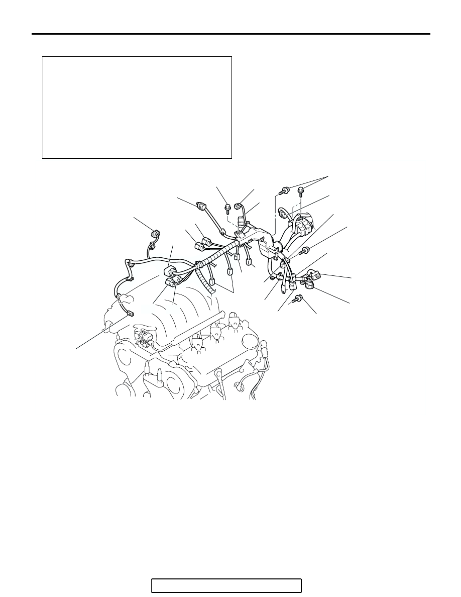
REMOVAL STEPS
1.
LEFT BANK HEATED OXYGEN
SENSOR (REAR) CONNECTOR
2.
LEFT BANK HEATED OXYGEN
SENSOR (FRONT) CONNECTOR
3.
RIGHT BANK HEATED OXYGEN
SENSOR (REAR) CONNECTOR
4.
RIGHT BANK HEATED OXYGEN
SENSOR (FRONT) CONNECTOR
5.
THROTTLE BODY ASSEMBLY
CONNECTOR
6.
EVAPORATIVE EMISSION
PURGE SOLENOID CONNECTOR
7.
MANIFOLD ABSOLUTE
PRESSURE SENSOR
CONNECTOR
8.
POWER STEERING PRESSURE
SWITCH CONNECTOR
9.
CONTROL WIRING HARNESS
AND WIRING HARNESS
COMBINATION CONNECTOR
10. KNOCK SENSOR CONNECTOR
11. CRANKSHAFT POSITION
SENSOR CONNECTOR
12. EXHAUST GAS RECIRCULATION
VALVE CONNECTOR
13. INJECTOR CONNECTOR
14. ENGINE COOLANT
TEMPERATURE SENSOR
CONNECTOR
15. CAPACITOR CONNECTOR
REMOVAL STEPS (Continued)