Mitsubishi Galant 9G. Manual - part 331
CRANKSHAFT OIL SEAL
TSB Revision
ENGINE MECHANICAL <2.4L ENGINE>
11A-40
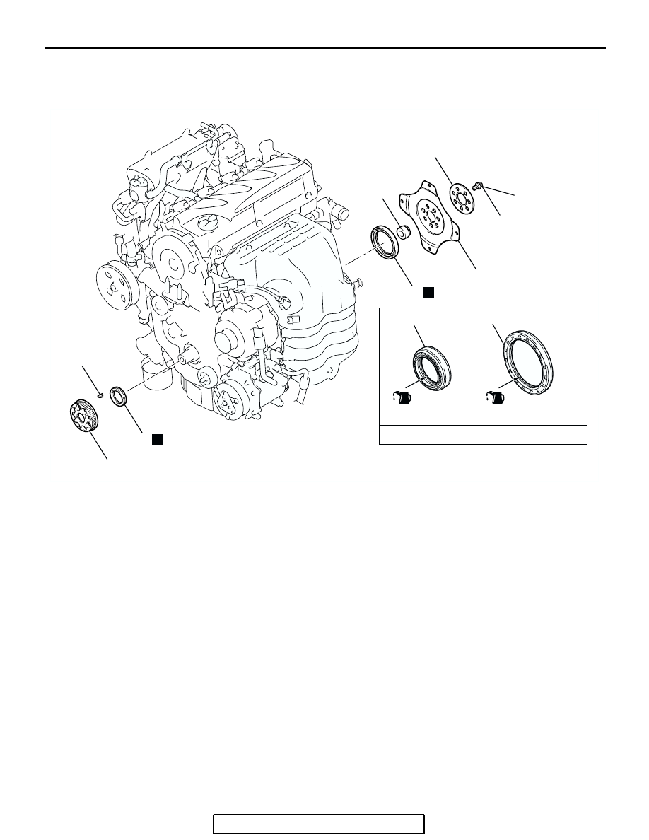
CRANKSHAFT OIL SEAL
REMOVAL AND INSTALLATION
M1112003100369
Required Special Tools:
• MB990938: Installer Bar
• MD998285: Crankshaft Front Oil Seal Guide
• MD998375: Crankshaft Front Oil Seal Installer
• MD998776: Crankshaft Rear Oil Seal Installer
• MD998781: Flywheel Stopper
AC306538
1
2
3
N
8
7
6
5
4
N
132 ± 5 N·m
98 ± 3 ft-lb
(LIP SECTION)
ENGINE OIL
AB
(LIP SECTION)
3
8
CRANKSHAFT FRONT OIL SEAL
REMOVAL STEPS
•
VALVE TIMING BELT AND
BALANCER TIMING BELT
(REFER TO
).
>>D<<
1.
CRANKSHAFT BALANCER
SHAFT DRIVE SPROCKET
2.
CRANKSHAFT KEY
>>C<<
3.
CRANKSHAFT FRONT OIL SEAL
CRANKSHAFT REAR OIL SEAL
REMOVAL STEPS
•
TRANSAXLE ASSEMBLY (REFER
TO GROUP 23A, TRANSAXLE
ASSEMBLY
<<A>>
>>B<<
4.
A/T DRIVE PLATE BOLTS
5.
A/T DRIVE PLATE ADAPTER
PLATE
6.
A/T DRIVE PLATE
7.
CRANKSHAFT BUSH
>>A<<
8.
CRANKSHAFT REAR OIL SEAL