Mitsubishi Galant 9G. Manual - part 329


  Index      Mitsubishi     Mitsubishi Galant 9G - service repair manual


Search            


Content   ..  327  328  329  330   ..


Mitsubishi Galant 9G. Manual - part 329


CAMSHAFT AND VALVE STEM SEAL

TSB Revision

ENGINE MECHANICAL <2.4L ENGINE>

11A-32

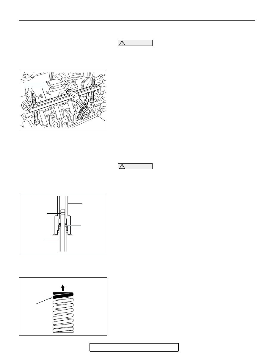
<<D>> VALVE SPRING RETAINER LOCKS 
REMOVAL

CAUTION

When removing valve spring retainer locks, leave the pis-
ton of each cylinder in the TDC (Top Dead Center) position. 
The valve may fall into the cylinder if the piston is not 
properly in the TDC position.
Use special tool MD998772 to compress the valve spring and 
then remove the valve spring retainer locks.

INSTALLATION SERVICE POINTS

.

>>A<< VALVE STEM SEALS INSTALLATION

1. Apply a small amount of engine oil to the valve stem seals.

CAUTION

• Do not re-use the valve stem seal.
• The special tool MD998774 must be used to install the 

valve stem seal. Improper installation could result in oil 
leaking past the valve guide.

2. Use special tool MD998774 to fill a new valve stem seal in 

the valve guide using the valve stem area as a guide.

.

>>B<< EXHAUST VALVE SPRINGS/INTAKE 
VALVE SPRINGS INSTALLATION

Install the valve springs with its identification color painted end 
facing the locker arm.

AC301867

AB

MD998772

AC308654AB

MD998774

VALVE

VALVE 
STEM 
SEAL

VALVE 
GUIDE

AC107415

AD

ROCKER ARM SIDE

IDENTIFICATION
COLOR
 INTAKE SIDE:
 LIGHT BLUE
 EXHAUST SIDE:
 ORANGE

CAMSHAFT AND VALVE STEM SEAL

TSB Revision

ENGINE MECHANICAL <2.4L ENGINE>

11A-33

.

>>C<< VALVE SPRING RETAINER LOCKS 
INSTALLATION

Use special tool MD998772 to compress the valve spring and 
then install the valve spring retainer lock in the same manner 
as removal.

.

>>D<< CAMSHAFT INSTALLATION

Set the dowel pin of the camshaft in the position shown in the 
figure.

.

>>E<< INTAKE ROCKER ARM AND SHAFT 
ASSEMBLY/INTAKE ROCKER ARM SHAFT CAPS 
INSTALLATION

1. Place the intake rocker shaft so that its 5.5 mm (0.22 inch) 

hole faces toward the cylinder head.

2. Install the intake rocker arm shaft caps.
3. Tighten the intake rocker shaft mounting bolts to the 

specified torque.

Tightening torque: 31 

± 3 Nm (23 ± 2 ft-lb)

.

AC301867

AB

MD998772

AC301868

AB

DOWEL PIN

AC301869

ENGINE FRONT

AB

φ 5.5 mm
(0.22 in)

CAMSHAFT AND VALVE STEM SEAL

TSB Revision

ENGINE MECHANICAL <2.4L ENGINE>

11A-34

>>F<< EXHAUST ROCKER ARM AND SHAFT 
ASSEMBLY/EXHAUST ROCKER ARM SHAFT 
CAPS INSTALLATION

1. Install the exhaust rocker shaft so that its notch is positioned 

as shown.

2. Install the exhaust rocker arm shaft caps.
3. Tighten the exhaust rocker shaft mounting bolts to the 

specified torque.

Tightening torque: 13 

± 1 Nm (115 ± 9 in-lb)

.

>>G<< CAMSHAFT OIL SEAL INSTALLATION

1. Apply engine oil to the entire inner diameter of the oil seal 

lip.

2. Use special tool MD998713 to press-fit the oil seal as 

shown. 

.

>>H<< CAMSHAFT SPROCKET INSTALLATION

1. Hold the camshaft sprocket with special tools MB990767 

and MD998719 in the same manner as removal.

2. Tighten the camshaft sprocket mounting bolt to the specified 

torque.

Tightening torque: 89 

± 9 Nm (65 ± 7 ft-lb)

.

AC301870

ENGINE FRONT

AB

NOTCH

AC102323AC

MD998713

CAMSHAFT OIL SEAL

(ENGINE OIL)

AC102532 AB

MB990767

MD998719

CAMSHAFT AND VALVE STEM SEAL

TSB Revision

ENGINE MECHANICAL <2.4L ENGINE>

11A-35

>>I<< CAMSHAFT POSITION SENSOR SUPPORT 
INSTALLATION

1. Remove sealant from the camshaft position sensor support 

and cylinder head surfaces.

2. Apply the sealant to the camshaft position sensor support 

flange in a continuous bead as shown in the illustration.

Specified sealant: 3M

 AAD Part No.8672, 3M AAD 

Part No.8679/8678 or equivalent

NOTE: Install the camshaft position sensor support within 15 
minutes after applying the sealant.

3. Install the camshaft position sensor support to the cylinder 

head.

CAUTION

Wait at least one hour. Never start the engine or let engine 
oil or coolant touch the adhesion surface during that time.
4. Tighten the camshaft position sensor support mounting bolts 

to the specified torque.

Tightening torque: 14 

± 1 Nm (120 ± 13 in-lb)

.

>>J<< ENGINE OIL PRESSURE SWITCH 
INSTALLATION

1. Remove sealant from the engine oil pressure switch and 

cylinder head surfaces.

2. Apply sealant to the thread of the engine oil pressure switch 

as shown.

Specified sealant: 3M

 AAD Part No.8672, 3M AAD 

Part No.8679/8678 or equivalent

NOTE: Install the engine oil pressure switch within 15 min-
utes after applying the sealant.

CAUTION

Wait at least one hour. Never start the engine or let engine 
oil or coolant touch the adhesion surface during that time.

3. Tighten the engine oil pressure switch to the specified 

torque as shown.

Tightening torque: 10 

± 2 Nm (89 ± 17 in-lb)

.

AC301268AB

φ 3 mm
(0.12 in)

AC304807AB

 1 mm
(0.039 in)

 5 mm
(0.20 in)

AC304808AB

ENGINE OIL 
PRESSURE
SWITCH


Content   ..  327  328  329  330   ..