Mitsubishi Galant 9G. Manual - part 324


  Index      Mitsubishi     Mitsubishi Galant 9G - service repair manual


Search            


Content   ..  322  323  324  325   ..


Mitsubishi Galant 9G. Manual - part 324


ON-VEHICLE SERVICE

TSB Revision

ENGINE MECHANICAL <2.4L ENGINE>

11A-12

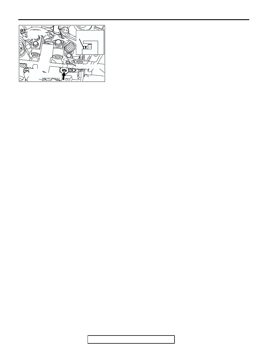
7. While shutting up the oil passage hole at the depth of the 

engine oil control valve's installation hole by finger not to 
leak air, blow compression air into the engine oil pressure 
switch's installation hole by air blowgun. At this time, confirm 
that the rocker arm piston can operate.

NOTE: To fully confirm the check, prevent the compression air 
from leaking as much as possible by installing the O-ring to the 
end of air blowgun.
8. Turn the crankshaft clockwise until the notch on the 

crankshaft pulley is lined up with "T" mark on the lower cover 
of timing belt.

9. Confirm the rest of the rocker arm pistons under the 

procedure 7.

10.When the rocker arm piston does not operate, replace the 

rocker arm assy.

11.Install the engine oil pressure switch and the engine oil 

control valve. (Refer to Camshaft and Valve Stem Seal 

− 

Removal and Installation 

P.11A-28

.)

12.Install the rocker cover.
13.Install all of the ignition coils.

IGNITION TIMING CHECK

M1111001701064

Required Special Tool:
MB991958: Scan Tool (MUT-III Sub Assembly)

• MB991824: V.C.I.

• MB991827: MUT-III USB Cable

• MB991910: MUT-III Main Harness A

1. Before inspection, set the vehicle in the following condition:

• Engine coolant temperature: 80 − 95°C (176 − 203°F)

• Lights and all accessories: OFF

• Transaxle: P range

NOTE: Vehicles for Canada, the headlight, taillight, etc. 
remain lit even when the lighting switch is in "OFF" position 
but this is no problem for checks.

AK302684AB

ROCKER ARM 
PISTON

BLOW 
COMPRESSION 
AIR

OIL PASSAGE

ROCKER 
ARM

ON-VEHICLE SERVICE

TSB Revision

ENGINE MECHANICAL <2.4L ENGINE>

11A-13

CAUTION

To prevent damage to scan tool MB991958, always turn the 
ignition switch to the "LOCK" (OFF) position before con-
necting or disconnecting scan tool MB991958.
2. Connect scan tool MB991958 to the data link connector.
3. Set the timing light to the power supply line (terminal No. 1) 

of the ignition coil No. 1.
NOTE: The power supply line is looped and also longer than 
the other ones.

4. Start the engine and run it at idle.
5. Check that the idle speed is approximately 700 r/min.
6. Select scan tool MB991958 actuator test "item number 17".
7. Check that basic ignition timing is within the standard value.

Standard value: 5

° BTDC ± 3°

8. If the basic ignition timing is not within the standard value, 

check the following items:

• Diagnostic output

• Timing belt cover and crankshaft position sensor installation 

conditions

• Crankshaft sensing blade condition

CAUTION

If the actuator test is not canceled, the forced drive will 
continue for 27 minutes. Driving in this state could lead to 
engine failure.
9. Press the clear key on scan tool MB991958 (select forced 

drive stop mode), and cancel the actuator test.

10.Check that the actual ignition timing is at the standard value.

Standard value: Approximately 10

° BTDC

NOTE: Ignition timing fluctuates about 

±

 7

°

 Before Top Dead 

Center, even under normal operating condition.
NOTE: It is automatically further advanced by about 5

°

 to 

10

°

 Before Top Dead Center at higher altitudes.

AC302077
AC305412

AC306958AB

MB991824

MB991910

MB991668

DATA LINK

CONNECTOR

ON-VEHICLE SERVICE

TSB Revision

ENGINE MECHANICAL <2.4L ENGINE>

11A-14

CURB IDLE  SPEED CHECK

M1111003500999

Required Special Tool:
MB991958: Scan Tool (MUT-III Sub Assembly)

• MB991824: V.C.I.

• MB991827: MUT-III USB Cable

• MB991910: MUT-III Main Harness A

1. Before inspection, set the vehicle in the following condition.

• Engine coolant temperature: 80 − 95°C (176 − 203°F)

• Lights and all accessories: OFF

• Transaxle: P range

NOTE: Vehicles for Canada, the headlight, taillight, etc. 
remain lit even when the lighting switch is in "OFF" position 
but this is no problem for checks.

CAUTION

To prevent damage to scan tool MB991958, always turn the 
ignition switch to the "LOCK" (OFF) position before con-
necting or disconnecting scan tool MB991958.
2. Connect scan tool MB991958 to the data link connector.
3. Check the basic ignition timing.

Standard value: 5

° BTDC ± 3°

4. Start the engine.
5. Run the engine at idle for 2 minutes.
6. Check the idle speed. Select item number 22 and take a 

reading of the idle speed.

Curb idle speed: 700 

± 100 r/min

NOTE: The idle speed is controlled automatically by the idle 
air control system.

7. If the idle speed is outside the standard value, refer to 

GROUP 13A, Multiport Fuel Injection (MFI) <2.4L Engine> 

− 

Multiport Fuel Injection (MFI) Diagnosis 

− Symptom Chart 

P.13A-38

.

AC302077
AC305412

AC306958AB

MB991824

MB991910

MB991668

DATA LINK

CONNECTOR

ON-VEHICLE SERVICE

TSB Revision

ENGINE MECHANICAL <2.4L ENGINE>

11A-15

IDLE MIXTURE CHECK

M1111002100749

Required Special Tool:
MB991958: Scan Tool (MUT-III Sub Assembly)

• MB991824: V.C.I.

• MB991827: MUT-III USB Cable

• MB991910: MUT-III Main Harness A

1. Before inspection, set the vehicle in the following condition:

• Engine coolant temperature: 80 − 95°C (176 − 203°F)

• Lights and all accessories: OFF

• Transaxle: P range

NOTE: Vehicles for Canada, the headlight, taillight, etc. 
remain lit even when the lighting switch is in "OFF" position 
but this is no problem for checks.

CAUTION

To prevent damage to scan tool MB991958, always turn the 
ignition switch to the "LOCK" (OFF) position before con-
necting or disconnecting scan tool MB991958.
2. Connect scan tool MB991958 to the data link connector.
3. Check that the basic ignition timing is within the standard 

value. 

Standard value: 5

° BTDC ± 3°

4. Start the engine and increase the engine speed to 2,500 

r/min for 2 minutes.

5. Set the CO, HC tester.
6. Check the CO contents and the HC contents at idle.

Standard value:

CO contents: 0.5 % or less
HC contents: 100 ppm or less

7. If the CO and HC contents do not remain inside the standard 

value, check the following items:
NOTE: Replace the catalytic converter when the CO and HC 
contents do not remain inside the standard value, even 
though the result of the inspection is normal for all items.

• Diagnostic output

• Closed-loop control (When the closed-loop control is carried 

out normally, the output signal of the heated oxygen sensor 
changes between 0 

− 400 mV and 600 − 1,000 mV at idle.)

• Fuel pressures

• Injector

• Ignition coil, spark plug

• EGR system

• Evaporative emission system

• Compression pressure

AC302077
AC305412

AC306958AB

MB991824

MB991910

MB991668

DATA LINK

CONNECTOR


Content   ..  322  323  324  325   ..